Saturday 7 March 2015

how to hack airtel digital tv set top box

Hack Airtel Digital TV for free

HOW TO SCAN ALL THE FREE TO AIR CHANNELS OF AIRTEL DIGITAL TV


HOW TO SCAN ALL THE FREE TO AIR CHANNELS OF AIRTEL DIGITAL TV 


Hi Guys ! Today i will tell you how we can scan all channels available on Airtel digital Tv using ADTV Set top box.
You don't need any FTA set top box , you can scan all channels by using your own ADTV Set Top Box . Just follow these simple steps ..
Open menu--->
Settings--->
System setup--->
Free to air channels--->
Find channels--->
  
 Satellite: Choose any(Insat 4A ,4B or other)
Search mode: FTA+CAS
Transponder: USER
Modulation type: DVB-S2-QPSK
Frequency:11480
Polarization : VERTICAL
Symbol rate:28800
FEC: 2/3(or any)
Fill these details and press blue button to search the channels , you will see a list of all channels available on this transponder.


Follow the same procedure , only change the given detail ,other fills will remain same.
frequency: 11561
polarization : horizontal and vertical (check both)
symbol rate: 28800
frequency: 11680 
polarization : vertical 
symbol rate: 28800
 

frequency: 11483 
polarization : horizontal
symbol rate: 25600

frequency: 11521
 
polarization :horizontal and vertical(check both)
symbol rate: 28800

frequency: 11600 
polarization : horizontal and vertical (check both)
symbol rate: 28800

HOW TO SEE TATASKY SHOWCASE TRICK

1. Go to ur Showcase and chose any movie
and active..ur Tatasky balance below 20rs
2. Tatasky send message on ur register mob number ur Showcase movie charge is 50rs u send yes
3. Point just out ur digicard in digicom
4. 5to 20minutes then Tatasky send msg on ur mob Showcase activete then on ur Tataskyand enjoy movie for 24hrs


Searches related to how to see tata sky showcase trick tata sky hack tricks tata sky tricks 2014 tata sky tips and tricks tata sky showcase timings tata sky showcase 3d tata sky showcase tamil movies tata sky showcase movies list tata sky showcase cost how to hack tata sky free tata sky recharge hack how to hack tata sky set top box how to hack tata sky channels how to refresh tata sky tata sky hack trick 2014 tata sky hack crack how to hack tata sky hd channels

TATA SKY AGAIN HACKED IN KOLKATA AND M.P

TATA SKY AGAIN HACKED IN KOLKATA AND M.P IN 0 OR NEGETIVE BALANCE 100% WORK..
1st on ur Tata Sky then click any chanel 30 to35 times its called norecponce don't worry then go to setting>frequency then set frequency 5000f 5500f this time u click 5times as u like channel to its chanel ar automating unlock 4 lifetime hurry...
Note: This trick only 4 kolkata and m.p ar succesfully working..


Searches related to how to see tata sky showcase trick tata sky hack tricks tata sky tricks 2014 tata sky tips and tricks tata sky showcase timings tata sky showcase 3d tata sky showcase tamil movies tata sky showcase movies list tata sky showcase cost how to hack tata sky free tata sky recharge hack how to hack tata sky set top box how to hack tata sky channels how to refresh tata sky tata sky hack trick 2014 tata sky hack crack how to hack tata sky hd channels

how to watch tata sky without recharge

AGAIN TATASKY TRICKZ WITHOUT RECHARGE
I am back with new tata sky trick..tum log tatasky ko free me recharge kar sakte ho apne purane use kiya hua recharge card se. ap jante hi ho tatasky ne naya software update kiya hai 2.0/beta mario..trick esh trahhai..
1>ek recharge card lena purana use kiya hua.
2> phir tum setting>update>software jake software ko lock kar dena 000000 dabake to default software activate ho jayega..
3>phir jo recharge card main 16digit pin hota hai uska last ke 2 digit hata ke jo recharge card ka id hoga vo laga dena or apne tatasky ka last digit id laga dena..aur recharge kar dena to tumhara tatasky invalidbatayega..aur 3hrs ke liye lock ho jayega after 3times..dnt worry jab tatasky 3hrs ke liye bandhoga tab tum digicom se digicard and signal wire nikal dena 45 to 60 min ke liy phir paheli signal wire laga dena uske 5 min ke bad digicard laga dena to wo..software default 2.0/beta mario hoga to usme 200rs or 250rs a jayenge..
Note: tum log es trick ko 2pm to 5pm ke bech karna..eh trick kolkata me 100%wrk hai..dusre state ka pta nahi bt tum log apne state me bhi try kar sakte ho syed tumhare state me bhi work kare...


Searches related to how to see tata sky showcase trick tata sky hack tricks tata sky tricks 2014 tata sky tips and tricks tata sky showcase timings tata sky showcase 3d tata sky showcase tamil movies tata sky showcase movies list tata sky showcase cost how to hack tata sky free tata sky recharge hack how to hack tata sky set top box how to hack tata sky channels how to refresh tata sky tata sky hack trick 2014 tata sky hack crack how to hack tata sky hd channels

Wednesday 4 March 2015

The cheap fire alarm circuit using infrared

This is the cheap fire alarm circuit that Use principle of infrared sensor smoke. When cause events fire. The principle is simple and affordable. Ideal for general home use.
“Fire” is a word no one wants to hear. Or would like to make it happen. Because it’s losses occurred.
Although the fire was not serious and indefensible If we do not underestimate.
Power lines and electrical equipment to last for good, so decadent, it should not cause it to happen.
An alarm circuit to know that fires has many form depending on the type of sensor that get to application, shuch as the radiation heat form, the smoke detectors. Which most of such circuits, often expensive and difficult to buy.
But this our fire alarm circuit use the infrared light system as smoke detector. So easily created. Save more than And of course work efficiency of 100%.
The our fire alarm circuit include 2 section, are 1. The master unit which is the alarm signal generator and notice to point fire. And (2.) is the detector point which Separate sub. for install various rooms up to six points. And may be extended over a number of the detector point. If you have a large home and has room more than 6 rooms
Characteristics circuit active as shown in Figure 1.
How This Circuit works
In Figure 1 is master unit circuit which consists of the power supply circuit Including Transformer-T1 will reduce voltage at home to 6 volts at secondary, the Diodes -D1,D2 is connected as full wave rectifier by have capacitor-C1 is filter to smooth voltage.
The-cheap-fire-alarm-circuit
Figure 1 The cheap fire alarm circuit
IC1 serves as the frequency generator of 1.5 Hz to get output at pin 3, then to collector of Q1 by normal input at base of Q1 will be 0. Since working of the inverting IC2. But in the event of Fire the output of inverting will be positive. Cause transistor-Q1 work to bias drive base of Q2 runs. The buzzer that connect at collector will sound fully to alarm will know immediately that fire! By we can know that Occur at any point. By looking at the tube, LED D3-D9.
In case you want to connect buzzer or the alarm circuit for example sirent etc, There are more efficient that use in this circuit has small size so may increase current output with connecting the relay circuit in to circuit as Figure 2 Replace existing doorbell circuit.
modifying-the-circuit-to-use-with-the-high-current-load
Figure 2 modifying the circuit to use with the high current load.

At the inverting input of IC2 will connect to the sensor section at collector pin of Q9 as shown in Figure 3
the-detector-circuit-section
Figure 3 the detector circuit section.
In the heart of the sensor circuit is the Infrared transmitter (D10) and Infrared Receiver (Q10).
In normal operating conditions. Infrared light from the transmitter will be shined to the Receiver Making receiver has an impedance lower down. voltage at base of Q9 will low, making transistor-Q9 not work. The voltage at collector will have high value equal voltage at point A.
The voltage will cause the output of IC2 is 0. And while transistors-Q3-Q8 will not work.
In the event of a fire. The smoke to obscure the infrared beam Can not pass to a receiver, or a quantity less. The resistance of receiver will rises up, cause the voltage at base of Q9 is positive. The Q9 will work voltage at collector will reduce (as low)
Fire up that first set. The voltage at inverting input pin 1 will have low level , cause get the output at pin 2 is positive passed diod-D11 to base of Q1 make Q1 work as above.
Meanwhile, low voltage is fed through R4 to base of Q3 cause Q3 work, The LED-D3 will glow, making us more aware of the fire.
The advantages of this detector is in case of fire a wire to the sensor broken down This alarm also working.
How to builds
First of all assemble the components, the circuit, on the PCB, as shown in Figure 4. By assembly equipment in the correct finished Then the experiment circuit together to test the functionality.
single-sided-pcb-layout-and-components-layout
Figure 4 The Single-sided PCB layout and components layout
Testing may be done by spraying smoke into the box at the receiver, or Try to find a paper shade, the circuit to work immediately.
Finished deployment By the master unit may be installed inside the bedroom or That think that people in the house to hear the most obvious warning sign.
For the detector Should be installed at the top of the wall or ceiling Above the critical point is expected to be on fire, like a fireplace, sofa, rug, etc. as possible.
The components List
IC1___NE555___Timer IC___________= 1 pcs.
IC2__CD4069_____Inverter CMOS IC___= 1 pcs.
Q1,Q9___BC547__ 45V 100mA NPN Transistor
Q2___BC337__ 50V 800mA NPN Transistor
Q3___BC557__ 45V 100mA PNP Transistor
Q10__P1D1
C1____1000uF 16V____Electrolytic capacitors
C2____1uF 50V_____Ceramic capactors
C3,C4___0.1uF 63V___Polyester capacitors
D1,D2___1N4002___100V 1A Diodes
D3-D9_____LED
D10_______IR Tx.
D11-D16___1N4148____ 75V 150mA Diodes
R1_______100K____Resistors 1/4W 5%
R2_______470K____Resistors 1/4W 5%
R3,R17____47K_____Resistors 1/4W 5%
R4-R16____1K________”______”____”
R18______10K________”______”____”
R19,R20___100________”______”____”

Alarm light circuit for battery charger

This is Alarm light circuit for a general battery charger. It is simplified circuit and cheap, use one transistor BC557 and display with 2 LED.
Battery that use with car, motorcycle or Lamps lighting of fishermen. Always is Lead-acid batteries. Which each cell in the battery will have the voltage per cell is about 2.3 volts.duration of charging depends on current charging. By the currentmuch takes quick charger or less currents charge time is long. Between that charging the current will reduce continuously until the lowest is about 10mA. Which battery is near full charge. But we cannot know that battery full or not. because no signal alarm.
The circuit in Figure 1 is alarm light circuit for battery charger. By while charge battery will has the green light show all time. And will go out when full charged. Which the green LED because the transistors-Q1 works. Since while charge will has current provide Enough to circuit. And has resistors-R1, R2 to set bias to transistors. The Diode-D1 limits the voltage exceeds 0.7 volts.
Alarm-light-circuit-for-battery-charger
Figure 1 The alarm light circuit for battery charger
When battery is fully charged the green LED1 goes off. Because Currents stops flowing or may flow less than 10 milliamperes. But LED1 green may be extinguished, because the wrong battery polarity, short circuit at an output. The LED2-red will glow when the wrong battery polarity.
This circuit can use with the charger that can provide charge current between 1-3 amperes. If provide current charger 1 Amperes then provide use D1-1N4001-Diode, or if is 3 amperes also use diode 1N5401 instead. The resistors-R3 of 470 ohms will be used with the Rechargeable battery of 6 volts, if change as 680 ohms resistors to use for the battery 12 volts
How to builds
This project is not used many components so can assemble on the universal PCB board as Figure 2
In the assembly circuit, Starting equipment lowest first such as Diode and then resistors and sort of high continuously.
For the device has various polarity should be careful in the assembly circuit. Before placing these components will must set the polarity at PCB and the part match together because If you put backward, may cause equipment or circuit damage. How to check polarity and input device.
components-layout-of-this-projects
Figure 2 the components layout of this projects
The soldering iron is less than 40 watts. And Use of lead solder containing lead and tin in the ratio of 60/40. Including the need also to have a flux inside the lead.
The after that put the components and completely solder. to check correctness again But if you enter the wrong position. Should use a desoldering pump or a Desoldering remover To prevent damage to the PCB.
The components List
Resistors size ¼ watts +5%
R1_________56 ohms
R2_________100 ohms
R3_________470 ohm (680 ohm)
Semiconductors
D1_________1N4001 (1N5401)
D2, D3_____1N4148___ 75V 150mA Diodes
LED1______5mm Green LED
LED2______5mm Red LED
Q1________BC557B__ 45V 100mA PNP Transistor
Others components.
The universal PCB board.

Door Guard Knob Alarm circuit.

Door Guard Knob Alarm circuit.
This is Door Guard Knob Alarm circuit with touch system. When thief caught on the door handle, makes it sound an alarm once. Use the the detector capacitance within the body.This project is a small and economical. Ideal for travelers or those who want security.
How does it works
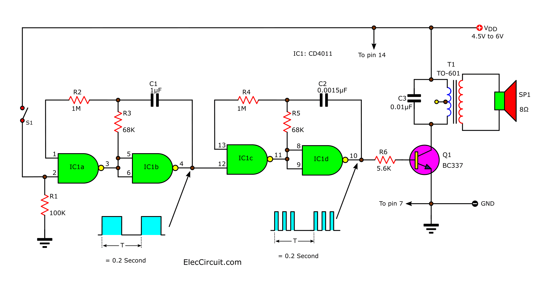
The circuit working as Figure 1 a 9V battery there are the regulator to reduce voltage down to 5V . Which consist of a transistor-Q1,R1 and ZD1 serves as provide to some circuit. In circuit include the frequency generator of three set. Firstly set have L1,C2,C3 and Q2, the signal is coupling with C4, then them are bypass a negative range go out with D1 so have only a positive signal range to bias Q3.
components-layouts-of-door-guard-knob-alarm
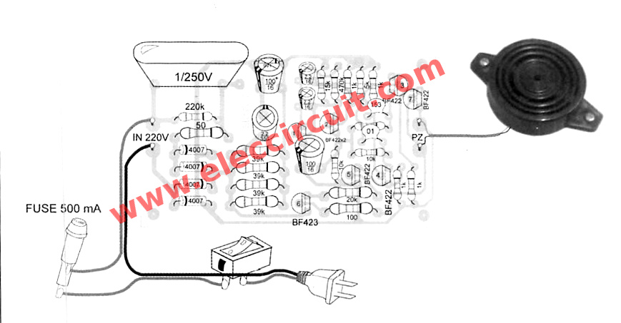
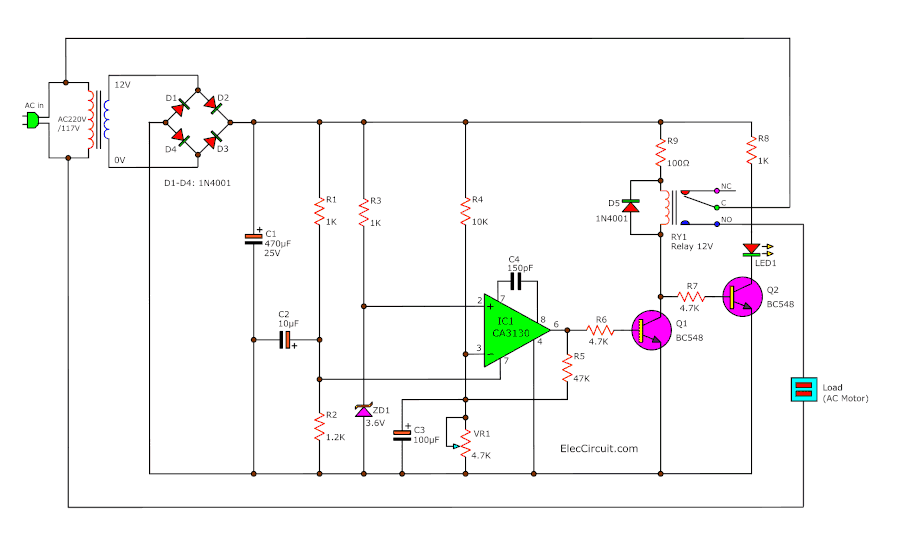
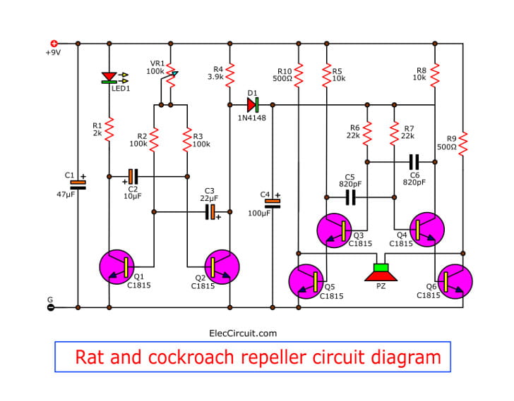
Figure 1 Door Guard Knob Alarm circuit.
We can adjust a sensitivity of project with changing resistance at collector lead of Q3 at resistors R4/1, R4/2. When Q3 works, pin 9 of IC1/1 which is inverter is connected to ground. The output pin 8 so is “1″ then through divide the voltage with R11 and R7 into bias for transistor-Q4 voltage from pin 8 of IC1/1. And some voltage will through C7,R8,D2,R9,C6,IC1/2 and R10 to bias for transistor-Q2
At the same time in normal state,which yet no hand touch to a knob door (connected with a check point) The working of transistor Q2, Q3 and Q4 will as above, that are Q4 act as on-off switch. To control operation of frequency generator of set 2 and 3.
Which if Q4 works (switch on circuit) The frequency generator of set 2 and 3 will do not work. Thus so no sound single anything loundly to peizo-PZ1
Suppose Hands of thieves touching door knobs. Nature of the body as a capacitor connected parallel with L1 and C2, cause the first frequency generator section stop working down. So no any signal through C4 come to bias transistor-Q3,
At pin 9 of IC1/1 there state “1″, But at pin 8 changed state is “0″ cause Q4 without bias (switch off circuit)
When Q4 do not works. The frequency generator of 2 section. Which consist of IC1/3, IC1/4,R13 and C8 will generate low frequency signal.
Which this signal will be bias to Q5. Therefore Q5 so work briefly. The transistor-Q5 will be controller working of This frequency is a resonance with Piezo-PZ1, Makes it sound an alarm intermittently.
How to build circuit.
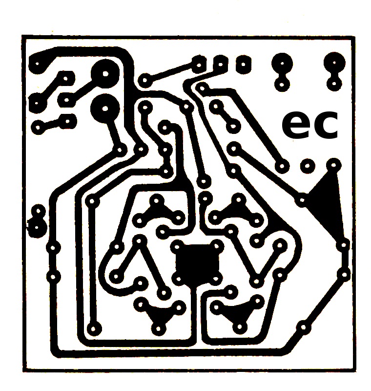
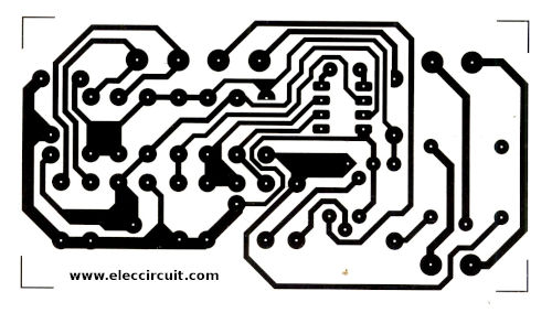
Copper layout size as actual on Figure 2. Firstly, required the equipment to complete before. For L1 that use wire No. 30-32 on IF form coil about 20 turns(IF coil of FM radio).
The components list.
Resistors
R1,R6________10K_____________= 2 pcs.
R2,R5,R8,R9____1M____________= 4 pcs.
R3__________5.6K____________= 1 pcs.
R4/1________330K____________= 1 pcs.
R4/2________1.8M____________= 1 pcs.
R7,R12,R16____100K___________= 3 pcs.
R10__________150K___________= 1 pcs.
R13__________620K__________ = 1 pcs.
R14__________1K_____________ = 1 pcs.
R15__________47K____________ = 1 pcs.
Capacitors
C1______33uF 16V___Electrolytic__1 pcs.
C3______10pF 50V____Ceramic_____1 pcs.
C4______330pF 50V___Ceramic_____1 pcs.
C5,C7,C8__0.1uF 50V___polyestor____3 pcs
C6______ 10uF 16V____Electrolytic__1 pcs.
C9______0.01uF 50V___Ceramic_____1 pcs.
Semiconductor
D1-D4____1N4148 Diode___________4 pcs.
Q1,Q4,Q5,Q5__CS9013 Transistors___4 pcs.
Q2,Q3_______CS9018 ___”________2 pcs.
IC1_______CD4069__Inverter IC____1 pcs.
Other
PZ1 piezo-No. KPE-133
L1 see text.
L2 see text.
etc…
For L2 use small output transformer by use only side 3 leg. But the real does not use the the middle leg.
The piezo is a KPE-133 model. Which is a three leg version. And there are resonance frequency of 3600 Hz. We can choose to use a different version of it. But must have leg of equal size, and resonance frequency is similar.
The switch-S1 is a 6 lead type (The 3-way rocker) Rocking up – middle – rocking down. The position “OFF” in the middle. The legs of the switch should be long enough. If soldering to the PCB, Lever broke through Panel must be fitted. But if you can not find a model with long leg, so hold S1 with the panel, then wiring to PCB board.
components-layouts-of-door-guard-knob-alarm
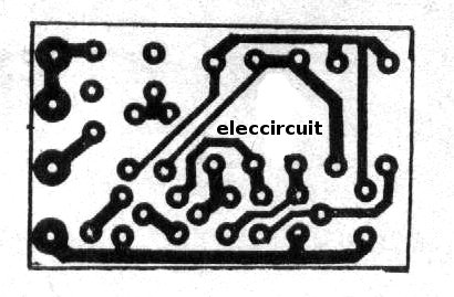
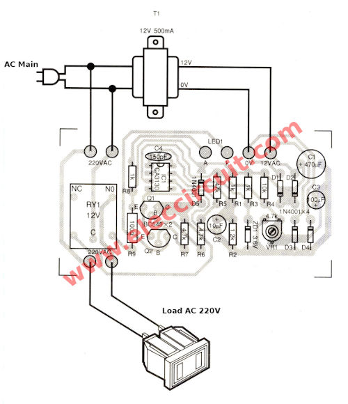
Figure 2 Single sided pcb layout.
Additional equipment required is a “bracelet”. Which are used as detector. To opt for a type conductors only. Hanging by This burglar project a touch with doorknobs.
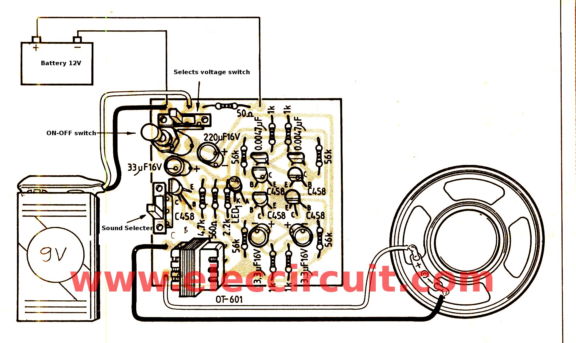
When have component due amount. It assembly a device on the PCB. Started, the device short first, followed by the device higher up respectively. By see the components layout on PCB in Figure 3.
components-layouts-of-door-guard-knob-alarm
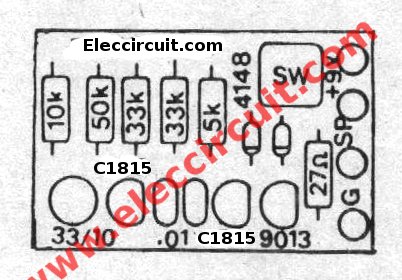
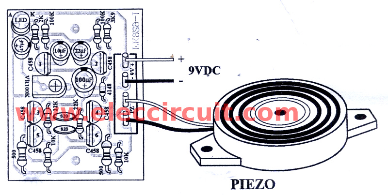
Figure 3 The components layout.
At detect point that Connected to one end of the bracelet. The rest of the bracelet left. Not be connected to the electrical pathway on Printed circuit boards.
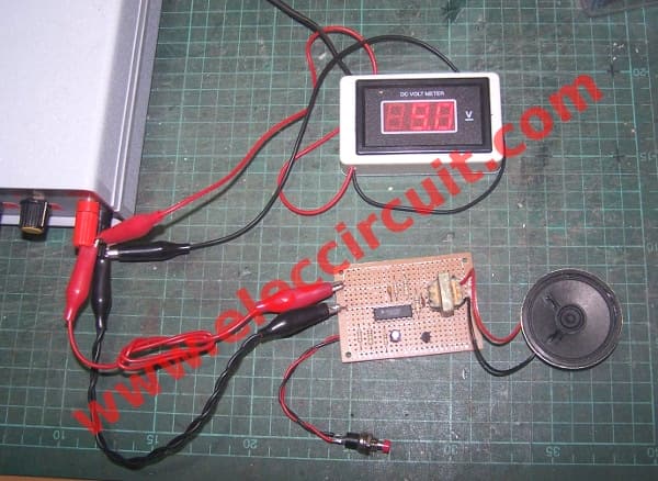
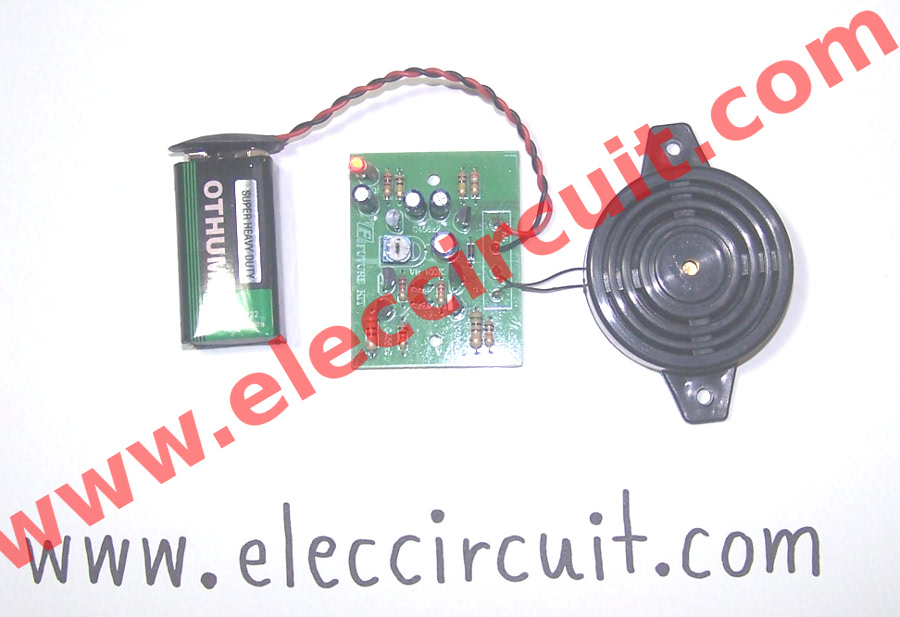
For 9 volts battery in Prototype was attached to the Panel of the machine. Using plastic as their hold. The Printed circuit boards attached to the back of the box. The height of the Printed circuit boards of must box is too high.
The applications
When you go in room and Locking knob, Followed by pressing the latch bolt. But still not sure. The need for this project. Ensure that this time you can sleep comfortably.
Applications simply use the chain strap knob inside. Then move the switch-S1 to position “High” or Was changed to use the variable resistors instead. But must to be close to the circuit.
Some may be Notice that If the thief gloves. This machine is working properly.
See product in amazon…

Two tone door buzzer using transistors

This is a two tone door buzzer, which is an electronic buzzer types,but them has melodic sound than the general electric bell. Which many people have seen the two tone bell sounds from other electronic journals.
But they are circuit that made no who apply them, since Problems three reasons:
1.First, while do not press a switch, the circuit also still have a lot of current consumption around up to several tens of milliamperes.
If will make on-off switcher, a power supply of circuit will must add other one switch individually. When we will press the buzzer we must press the other switch before, then when press completely the buzzer switch, we must close power switch again. To set to application as begin.
2. Secondly, the output sound is real two level. But the sound is vibrant and clear.
3. Thirdly, Suppose that solving the problem on-off switch,with replace an old battery with a DC adapter to circuit.
But the providing the power supply to circuit all the time that may making IC has heat and fast damaged, because those circuit use IC as the sound generator and they have more many cost than transistors.
So some companies ever produced a two tone buzzer kit to sell. But now out of production to Because of Problems mentioned above.
But for this two tone door buzzer that I would like to introduce you build them, which as circuit are designed become to solve all those.
If you do not press the buzzer switch, the circuit will not use the Low power consumption, by not must have on-off switch individual. And though while press the buzzer switch, the circuit will use low current so long time apply though is use by the normal battery.
Another issue, the circuit is designed to use all the transistors. In addition will clear, melodious and resonant voice. And creating cost savings as well. Because the transistors has very cheaper than ICs.
The working principle of circuit
In circuit diagram as Figure 1 will see that we use both transistor are connecting as the oscillator circuit on multi vibrator form. To crease a square wave signal then send to amplify in the next transistor before,to provide the signal high up then enter to the speaker.
the-circuit-diagram-of-the-two-tone-door-buzzer-using-transistors
Figure 1 the circuit diagram of the two tone door buzzer using transistors.
Observe the circuit to generate the sound. Sound frequency is determined by the value of Resistors and Capacitors. Here we use the C-0.01uF is constant.
So if we change the value of Resistors, Frequency of sound will go to change. Which Resistors in circuit has two set are R-33K quantity = 2 pcs. And Resistors R-50K other one.
While when we press switch, which is the pushbotton switch, current will flow through separated into two ways.
First way, flow through Diode-D1 go to charge in the capacitor-33uF 10V and while is also supply the current to Collector lead of both transistors.
Final ways, current will flow through diode-D2 in to common joint of R-33K to bias to base lead of both transistors.
In while both transistors will can oscillate, because have fully bias and frequency that get from usage this resistor-33K will be 2,200 Hz amplify out of speaker into high frequencies.
When we release the switch will no current flowing through both diode but will also has some current that still charge in capacitor-33uF 10V.
Which it will discharge out of the power supply to the oscillator circuit. But in while current in the base circuit will must pass both resistors-33K and 50K are mixed into 83K. When they have high resistance cause low frequency, from Calculated to be approximately 800 Hz. And This capacitor of 33uF 10V will fully discharge within time about 1.5 second. The oscillator will stop working,the speaker will go silent.
I concluded that, when press switch will be sound at frequencies of 2,200 HZ
Switch is released, it will sound frequency of 800 Hz is about 1.5 second. So, we will have the two tone door buzzer as you need.
The building and application.
This circuit have a printed circuit board copper foil track layout of this project. (actual-size) as Figure 2, For building also still same general circuit (as Figure 3) is put a low components before example: Resistors, Diode, Capacitors, Transistors sequence.
actual-size-bottom-side-of-two-tone-buzzer-layout
Figure 2 Actual-size,Single-sided PCB layout
the-top-bottom-components-layout
Figure 3 the top bottom components layout.
The speaker is used with size of 2 inchs 8 ohms 0.25 W to The compact But it applies to the other sizes.
This circuit use 9 volts power supply, All resistors use size ¼ W, switch use pushbutton types,and transistors; use number C1815,C828, or others NPN transistors. other parts see in circuits.

Car forgot turn off headlights alarm

If we forget to turn off the lights in the car or headlights on all night but in the morning you could not even start the car Because batteries lose some voltage, we lets to build the warning forgot off lights circuit better.
headlight-alarm-circuit-using-cd-4023
As perfect circuit in Figure 1. Use CMOS-IC no-MC14023B. Which is a NAND gate 3 input, Quantity: 3, a small transistor and a Buzzer only.
When rotate the car ignition key switch to stop the engine. If turns off the small headlights and opening the door out of the car, warning buzzer will sound immediately.
circuit-block-ideal
The working principle.
The working of circuit in Figure 2. This circuit use all NAND gate, We see the conditions that the buzzer has three reasons.
1. Rotate the Car ignition key switch to stop the engine. If engine not works also no voltage to charges the car battery. The voltage at switch should of 0-volts or state is “0”.
2. Forgot turns off the small headlight show that headlight still current and voltage at it should has about of 12-volts or state is “1”.
3. Opening the door to get out the car. The voltage may be 12 volts or 0 volts as each brand cars. Suppose the voltage is “0″, or state “0″ and conditions third item is the input signal to our circuit.
Then we see the 3 NAND gate input that we use. This gate is NAND, so if input is all “1” state, will be output equals “0” and it is the only case to the output is “0″.
If others input will has output is “1” all the times.
Use this features we will use this conditions cause the buzzer loud.
In when we need “1” so we need to reverse the logical state “0″ to “1″ by inverter. Which in this case we use others NAND into inverter form to saving IC.
See in Figure 2. We will use NAND gate- I2 inside MC14023B is are a decision making logic circuit. For I1 and I3 will be use as inverter gate to reverse the logical state of an incoming signal.
In Figure 1 from terminal A, which will wiring to headlight switch. If forgot turns off switch will has voltage is 12 volts. Therefore, is signal “1”. This signal will be connected to pin 1. Which is directly input of I2-NAND gate. The terminal B, which is connected to the door switch, the signal this terminal is “0”, if the door is opened and the lamp in car is brightness, this signal will be connected to through the I1-NAND gate, to reverse signal from “0” into “1”, Then so entered in the input of I2 next.
In addition,the door switch of some brands may be connected with a 12 volts or state “1”. We need to modify our circuit by connect this signal to input of I2 as Figure 2. Therefore, your car in which form, should check it before assemble this project.
For the the car ignition key switch will connect to the terminal C, this signal will has voltage is 0 volts. If stop engine. When is signal “0” so connect through I3 to reverse signal into “1” then in to I2 again.
The output of I2, which is pin 8 that is As a result, the decision conditions to be used to the buzzer loud. If we want to buzzer loud when output is “0”, so use how to connecting through resistor to drive the 2SC561- PNP-transistor.
When signal is “0” will has current flow from the power supply through emitter – base ,resistor in to the gate. This current will be amplify as collector current to drive buzzer.
If output is “1” or voltage is 12 volts. Which equals the power supply voltage also will noting have current flow in this section the buzzer so not loud.
In circuit has connecting as accessories for example: Resistor, Diode , R1 are connected to protects a high voltage which may be the start switch.
The R2-R4 are resistors that connects to protect when Input is left alone Because the switch Prevent electrostatic influence by reduce resistance input of CMOS down to same the resistors only.
The 1N4001-diode is connected to protect a noise signal while running which Which may be interrupting the operation of the circuit.
The case of Figure 1, there is NAND I1, which is not in use. Usually the gate is not in use, do not leave it and let the input. because the CMOS has very high input resistance. May be static or interference Itti’s easy. Should be connected to ground or the power supply.
the-components-layouts
The circuit assembly.
Figure 3 is the component layout on the perforated PCB and wiring, For ICs, transistor, and diode will use others that has any features comparable, Resistors size ¼ watts Precision, 5, 10 or 20%. The buzzer is small size at 12 volts and current less than 100 mA.
Soldering the wires on pcb should be tight.If the this handset equipped with a vibration in the car all the time. Wires may be detached easily. Should be soldered IC on PCB directly over the IC socket.
Creating a project It is not difficult But is installed on the car is the more difficult, which would be a function of your friends, if you want to do this project.
The circuit is successful
The component list.
IC1____MC14023B or TC4023 or CD4023____= 1 pcs.
Q1_____ 2SA561 or BC327 45V 800mA PNP Transistor___1 pcs.
D1_____1N4001____1000V 1A Diodes _______________= 1 pcs.
22K = 2 pcs.
100K____= 3 pcs
Buzzer 12V
The perforated board
Terminal,wires,and others.

American & Hong Kong police siren

Today I suggest siren circuit. Another circuit is very interesting. It can mimic the sound of a American police car and Hong Kong police. By which we use transistors mainly. For is so easy to buy equipment and budget.
How does it work.
In a Figure 1 will see that include of two sound generator set. First sound generator consist of Q1, Q2, C2, C3 and R1-R4. Then a second sound generator will include of Q3, Q4, C5, C6 and R7-R10. The sound signal will Different as level of parts in circuit.
American & Hong Kong police siren
Figure 1 The circuit diagram of a perfect American & Hong Kong police siren.
When a S2-switch is on “Hong Kong” position, the sound signal from a first series will out off from collector(C) of Q2 through R5 to controll working of the second sires. Which cause can get the output signal at collector of Q4 through R11 in to Q5 will be transformer-T1 by it is used to match the output of such circuits to a speaker.
If slide sw1 to “191” position will has also some sound signal through C4. A capacitance-C4 will cause feature of sound signal is changed.
How to build its.
You can assemble parts on the perforated board or universal board. But if you want to make PCB in permanent version. You can see in Figure 2 is actual-size of Single-sided Copper PCB layout. And Figure 3 is a components layout and wiring.
actual-size of Single-sided Copper PCB layout
Figure2 The Actual-size of Single-sided Copper PCB layout
components layout and wiring
Figure 3 The components layout and wiring
Application of this projects.
When assemble this project completely then to check for error, next apply the power supply 9-12volts, then test them by apply a 9-volts battery to the circuit. Next turn on power switch then press S2 we will hear a sound of siren from speaker anf LED1 flashes.
The applications can do many things. Such as be installed in the police car toy. Be installed on a motorcycle or a beep alarm for you.
The components list
Resistors ¼W +-5%
R1, R4, R7, R10—-1K ___________________ = 4 pcs.
R2, R3, R8, R9—–56K __________________ = 4 pcs.
R5——22K______________________________ = 1 pcs.
R6——560 ohms_________________________ = 1 pcs.
R11—–4.7K______________________________ = 1 pcs.
R12—–50 ohms___________________________= 1 pcs.
Transistors
Q1-Q5——————C458 or similar (C1815 or C828)___= 5 pcs.
Polyester Capacitors 50V
C5, C6——————0.0047uF ______= 2 pcs.

Electrolytic capacitors

C1———————–220uF 16V ______________________= 1 pcs.
C2, C3——————3.3uF 16V _______________________= 1 pcs.
C4———————–33uF 16V ________________________= 1 pcs.
T1————-OT-601 ____Output transformer___________= 1 pcs.
S1, S3——– SPDT- Single-pole, Double-throw switch__= 1 pcs.
S2————-normally pushbuttom____________________= 1 pcs.
Others
LED, speaker 8 ohms, PCB, Universal box.

Simple Electronic clock sound using IC4011

The sound of insects such as crickets, cicadas, resulting from flutter briefly. We can use a multivibrator to connects as sound generator circuit to imitate these insects sound.
Some electronic clock alarm tone also sounds similar to these insects. As Figure 1 is simple clock alarm sound generator that can assemble on a breadboard right away.
Working of circuits
As Figure 1 The circuit consists of two astable multivibrator, firstly include both gate IC1c and IC1d are used generate low frequency as the sounds of insect wings. A second also include with both gate IC1a and IC1b same simple tone generator using CD4011 which is higher frequency than first. And they are used to set rhythm interval of sound.
The output of multivibrator 2 (pin 4 of gate I2) will be controlled by the first astable multivibrator which generates the low frequency as the tone burst signal characteristics.
electronic-clock-sounds-circuit-using-cd4011
Figure 1
We control them switch continuously with oscillation and stop oscillation with low frequency about 5 Hz.
In this case we use signal “1” and “0” alternately. If state “1” will make the oscillation, but is “0” will stop the oscillation.
The Devices R and C astable multivibrator as circuit will get tone frequency about 600 Hz and Strokes will interval is about 0.2 Second. Please try modifying these to change the R and C melodic sound to listen up.
Components list
IC1____CD4011 Quad nand gate CMOS IC____= 1 pcs.
Q1____BC337____0.8A 40V NPN transistor______= 1 pcs.
T1____Small signal transformer________________ = 1 pcs.
R1____100K___1/4 watts 5%__________________ = 1 pcs.
R2,R4____1M______”_______”________________ = 2 pcs.
R3,R5____68K_____”_______”__________________= 2 pcs.
R6______5.6K_____”_______”__________________= 1 pcs.
C1______1uF 50V Ceramic capacitors_________ = 1 pcs.
C2_____0.0015 uF______”______”______________ = 1 pcs.
C3______0.01 uF_______”______”______________ = 1 pcs.
Speaker 8 ohms._____________________________ = 1 pcs.
How to builds
We experiment the circuit on a breadboard or assemble all components on Perforated board as Figure 2
assemble all components on Perforated board
The previous circuit low volume since piezo speaker which use high impedance so use low current consumption, but it low volume.
This circuit I need loud volume better the previous circuit. So use normal speaker 8 ohms 0.25 watt. But we cannot connect it to IC’s output directly.
We so use a small audio transformer to prevents the very low resistance of the speaker (8 ohms) from loading down the circuit and possibly even stopping its oscillation.
And there is transistor-BC337 to drive transformer, cause this circuit have very loud volume than one.
Switch S1 is used for turn ON/OFF tone generator.
Power supply voltage can use during 4.5V to 13V, This reduce the supply voltage and lowers the volume. As video below.

Morning alarm with sunlight using IC-4011

This is simple circuit that we makes in hobby time or toys for my son but really uses. It will have sound alarm when morning like a normal clock alarm with lighting sensor same clock. We use a IC-4011 CMOS only one and a few components also can generate pulsating tone like a general clock.
How This Circuit works.
As Figure 1 This circuit use the IC-4011 quad nand gate as main of circuit, it includes for separate positive logic nand gate on a single silicon chip. In circuit diagram consist of an oscillator circuit in astable multivibrator 2 set.
First set include of IC1a and IC1b, then second set include of IC1c and IC1d.
circuit-diagram-of-mornig-alarm-by-sunlight
Figure 1 is completely morning alarm with sunlight.
A R1 is LDR (Light Depended Resistor) or photoresistor which is a resistor type. The resistance of a photoresistor changes with the light intensity to strike them.
If no light strikes it.
This resistor R1 may have high resistance rises between 500K to 600K. And if have normal light (Common Fluorescent light.) The resistance will reduce is about 20K – 30K.
On the condition that LDR is getting light, because of its high resistance to more than the value of R2. The voltage at pin 1 of IC1a will lower half of power supply. This cause first oscillator does not work. So the second oscillator also not works. Therefore without sound out of speaker.
When LDR get light its resistance will reduce and voltage drop across it will reduce making voltage across R2 rises unless more than half of the power supply. It cause the first oscillator working to generate the output frequency.
So this frequency can determine with Resistor R1 and Capacitors C1
Frequency output = F = 1/(2.2R1C1)
Which we use value R1 and C1 as circuit above will get frequency about 4 Hz. At the same time the output of IC1b is state “1” will cause the second oscillator (include with IC1c, IC1d and R4, C2) cause have frequency about 900 Hz.
And if output of IC1b is state “0”, then the second oscillator will not works. The output of IC1d that is the tone burst signal as Figure 2.
the tone burst signal characteristics
Figure 2 the tone burst signal characteristics.
The transistor-Q1 (BC547) and Q2 (BC337) are connected as darlington compound to increase current upper. The resistor-R4 will reduce slightly volume of speaker. If you want to high volume sound you need to change value lower.
The capacitor – C3 (100uF 16V) across between positive and ground of circuit which acts as filter the pulsating voltage into into a steady direct current.
How to builds and application.
We can build this project easily, by solder all components on the perforated board and wiring as Figure 3 , Then you may will install them in the universal box. We drill aperture for LDR and potentiometer to adjust easily light sensitivity.
solder all components on the perforated board and wiring
Figure 3
When will assemble completely this projects. Then check for errors. Next, turns On to apply circuit. And then move LDR to light will hear alarm sound out of speaker.
Next, shade the photoresisitor cause sound stop. That R2 is adjuster light sensitivity of circuit,mean that we can set them to begin working at any light as we need.
As video below we test this in really uses.

The components List.
Resistors ¼ watts 5% (Unless otherwise specified.)
R1———-LDR (change value in range of 20K-600K)
R2———-VR 100K___Trimmer Cermet or Carbon
R3———-1M
R4———-500K
R5———-20K
R6———-20 ohms
Capacitors
C1———-0.1uF 50V__Mylar__________ = 1 pcs.
C2———-0.001uF 50V__ Mylar_______ = 1 pcs.
C3———-100uF 16V___Electrolytic____= 1 pcs.
Semiconductors
Q1———–BC547
Q2———–BC547,BC337
IC1———- CD4011 nand gate cmos
others
9-volts battery with in snap connector.
On/Off switches.
Speaker 8 ohms 0.5 watts
Wires, and others etc.

220V AC siren circuit

This circuit is a simple siren circuit that use 220V AC as power supply. It is small size and use a piezo speaker cause use low power and saving.
How it works
This circuit is shown as Figure 1 which we use power source by reducing AC-voltage of 220 volts down by the resistors-R1, R2 ; the capacitor-C1 act as coupling AC-voltage. Secondly, the current will rectifier into DC voltage by diode bridge D1-D4. And there is C2 function to filter steady DC current.
220v ac siren circuit
The some voltage will flow to emitter lead of Q5 and other will is sent to R3-R6 to reduce voltage to ZD1 before, which it will maintain the steady (DC) current regulated supply at about 9.1 volts. The capacitor-C3 will smooth or filter the pulsating voltage from a power supply into direct current.
To begin with press switch-SW1, the 220V AC voltage will reduced into 9.1 volts as power source of this circuit.
Both transistor- Q1 and Q2 are connected to a low frequency generator form, by output frequency depend on R7, R8, R9, C4 and C5.
When begin apply the power supply in to the circuit. The Q2 will works, at the same time C6 will start charge current. While transistor-Q2 is working, C5 will charging until voltage drop across C5 about 0.6 volts.
The transistor-Q1 will begin working cause Q2 stop. Then C4 start charging. At the same time it will pull current from B of Q1, so Q1 stop. Next Q2 will start renew again, Will be this indefinitely. The voltage at E of Q2 will charged to C6 and stop charging according to loop above. While Q2 stopped, C6 is discharged by R10 automatically.
The emitter lead ‘s voltage of Q2. In addition will charge the C6 is also supplied to B of Q3 and Q4. Which they are connected into an astable multivibrator circuit feature.
The operation of this project will start by Assume that the function Q4 (ON), located in the state of saturation and Q3 inactive (OFF). The C7 will be charged until the voltage across it is equal to the voltage of E of Q2.
While the Q2 performance, voltage at C of Q3 will increase, Until equal voltage from E of Q2. R13 serves to determine the size of the base current of Q4. To get the minimum, which makes Q4 can work in saturation.
Therefore it can be seen that when the capacitor-C7 capacitor fully. Q4 is working perfectly and is a state of saturation. And vice versa. When Q3 a state of saturation work. The capacitor-C8, it will keep fully charged, the voltage drop, equal to the voltage of E of Q2.
While Q4 is in the works to make positive of capacitor C8 becomes negative. All this work, will result in Q6 and Q7 working alternately.
When Q6 works, Q5 also works to follow with PZ1. There was a shake-up until it was pitched up. But when Q5 and Q6 stop working, Q7 will work instead PZ1 so gradually stopped shaking and the sound stopped.
How to Assemble this circuit.
Who created this project requires special precautions. It involves AC 220 V directly. First is to start making PCB as Figure 2. which actual-size of Single-sided Copper PCB layout. Making PCB should check the accuracy of the PCB before. Then Assemble parts when examining successfully. As Figure 3 Component layout for the PCB, Should be soldered from the low to the high, and if the device is a terminal. I need to see well before soldering.
actual-size of Copper PCB layout
Figure 2 The Copper PCB layout.
Component layout for the PCB
Figure 3 The component layout.
Testing
We should check for errors before. The external device as Figure 4. You should be very careful Because we are using the AC 220V directly. When the circuit is correct Then apply AC 220V to the circuit and turns on SW1. You can hear the sirens coming peizo speaker.
the application-of-ac-220v-siren
Figure 4 the application.
Components list
Resistor size: 0.25 watt +-5%
R2————–220K
R7————–15K
R8————–470K
R9, R14——–1K
R10, R13——10K
R11————-5K
R12————-33K
Resistor size: 0.5 waitt +- 5%
R1————–50 ohm
R3-R6———39K
R15————20K
R16———–100 ohm
Capacitors
C1————-1uF 250V AC/DC capacitor
C2————-2.2uF 350V_____Electrolyte
C3, C6——–100uF 16V_____Electrolyte
C4, C5——–2.2uF 50V_____Electrolyte
C7————-0.01 uF 50V____Ceramic
Semiconductor
D1-D4———–1N4007____1A 1000V Diode
ZD1————–9.1V 1/2W____Zener Diode
Q1-Q4, Q6-Q7—BF422_____Transistor or similar
Q5—————–BF423_____Transistor or similar
Other parts
FUSE1-Fuse 300mA set ——–1 set.
SW1-Switch AC—————-1 pcs.
PZ1- Piezo Speaker———-1 pcs.
U FB-17——————–1 pcs.
PCB,wires and others

Motor burn out and under voltage protection

This is AC motor burn out protection causes of under voltage input. The principle is simple, it will check for voltage at all times. Normal voltage is 220V AC. If the voltage falls below a preset. Relay will not work and the LED is a warning. Can be set to cut no-off in the voltage during the 168-227V.
As AC main in normal level, the relay will be connect to apply AC line to motor. And AC-line fall down lower than 10% of normal voltage the relay will cut of load at once. Until the voltage is restored to its original condition. So to get back into the circuit again. Ideally, blog diagram in Figure 1.
block diagram
Figure 1 the block diagram
The working of circuit.
As Figure 2 is a schematic of this project. There are an op-amp-IC1 as input voltage comparator, it will compare voltage between the reference voltage of ZD1- 3.6 volts zener diode , and input voltage from pin 3 of IC1 this voltage is divided by resistor-R4 and VR1.
We will set this voltage slightly lower than the reference voltage.
So this will apply a relay pulls in and connects AC electrical current to the motor or AC load.
The schematic of Motor burn out and under voltage protection
Figure 2 The schematic of Motor burn out and under voltage protection
The pin 3 will connected to capacitor C3 to reduce the fluctuating voltage to smooth. It may cause IC1, the relay-RY1 works with error. This will not be good for this circuit.
We will also connect the resistor-R5 across pin 6 and pin 3 of IC1, to set circuit in schmitt trigger form.
This is a special feature, it will cut off the load at once, when the AC main is under voltage into setting value.
If the main have ripple voltage,this will not works because the motor may be damaged.
Restarting with increasing AC voltage about 215 volts (as setting). So relay pulls in as Graph of time function in Figure 3.
Graph of time function
Figure 3
Reasons to Use IC1-CA3130 BecauseWhen conditions do not work, to make the output voltage is near 0 volts really. As a result transistor Q1 can not work absolutely.
But the common comparator ICs in not work state. The output voltage is 0.6 volts which may make the transistor can work.
The disadvantage of this IC is not able to tolerate the higher voltage 16 volts. Thus in this circuit we use voltage from the 15.8 volts power supply, then flow through the divider circuit of R1 and R2 cause have a 8.7 volts supply of IC1 only.
The transistor Q2 will drive LED to alert when under voltage until electric devices cannot work.
But in normal Q1 will ON cause voltage across Q2 is low so most current will flow to ground. Therefore, it is virtually no voltage to bias the Q2 As a result LED goes out.
Building
Before make the PCB as Figure 4 as copper pcb layout. Then soldering all parts on PCB as Figure 5 to begin with soldering low devices first for example: resistors, diodes then put higher parts down until connecting a transformer and more parts. Do not hurry, especially for pins to make sure the correct position. Then wiring the different positions.
Actual size of single sided copper PCB layout
Figure 4 Actual size of single sided copper PCB layout.
the components layout
Figure 5 the components layout.
This project will starting with input voltage AC 215 V, but relay will fast cut off the load when input fall to AC 198V by can adjust potentiometer -VR1.
Parts you will need.
Resistors ¼W +-5%
R1, R3, R8_______1K
R2______________1.2K
R4______________10K
R5______________47K
R6, R7___________4.7K
VR1- potentiometer__4.7K
Capacitors
C1__Electrolytic_____470uF/25V
C2__Ceramic__________10uF/16V
C3__Electrolytic_____100uF/16V
C4__Ceramic_________150pF/50V
Semiconductors
D1-D5___1N4001__1A 50V Diode
ZD1_____3.6V/0.5W Zener
Q1, Q2_____BC548___0.4A 40V NPN transistors
IC1________CA3130___
Others
RY1___Relay _____ 12V__1C
T1___Transformer__12V/0.5A
Box, PCB, Wires with plug 220V, etc.

Insect repellent device using ic 4047

This is a small circuit insect repellent, mosquitoes and birds, or other methods to produce high frequency audio signals. To interfere with the hearing of insects. Make it insufferable, wings to escape in the end.
Operation of this circuit is used IC1 number 4047. A duty to produce frequency. The frequency of IC1, set by VR1 and C1.The output at pin 10 and pin 11 alternately.If the output signal at pin 10 will cause transistors 03 and Q2 work.However, if the output signal to pin 11 will cause transistors Q1 and Q4 to work instead.So the speaker piano sound frequency in PZ1.
Insect repellent device using ic 4047

Mouse and insects repellent circuit using IC556

This is a mouse and insects repellent circuit, use high frequency out of the piezo speaker and IC-556 is base as oscillator between 22kHz and 56kHz
This projects is safer and more convenient than using chemicals to turn switch on only and use Low power consumption (only 0.5 watt) .
How This Circuit works
The working of this circuit is easy because IC1 is IC556 that has working principle resemble with IC555 there. So, the IC-556 have dual oscillator generators within an one IC, but IC555 has single oscillator only.
mouse-and-insects-repellent-circuit-diagram
In Figure 1 is completely circuit of Mouse and insects repellent projects.
The reason that we must use dual oscillator generators because the first section will bring to control voltage at pin 11 , which this voltage will control the IC changes from 22 Khz to 56KHz ,and this voltage has value is 1/3 to 2/3 of power supply.
When voltage change cause frequency also change. And this frequency is changed all time because mouse, rat, bug,insects and various animal have ability to a different frequency response. When frequency is changed in range 22KHZ to 56KHZ, makes we can repel a lot of the type of animals.
The IC1/1 will produce a base frequency by include C1, R1 and R2. Which there are frequencies to controls voltage at pin 11. And then the IC1/2 also serves as produce frequencies as same as it, that include C2, R4 and R5 but there are higher frequencies than IC1/1.
When pin 11 voltage changed since IC1/1 causes frequencies at IC1/2 now produce so changing from 22kHz and 56kHz there. The output will be connected to a piezo speaker which is the special speaker that responsible just higher frequencies only.
How to build this projects.
First search all parts before such as PCB, resistors, capacitors, etc. when finished ,then make the as same real PCB layout as Figure 2. Next, to assemble all components as Figure 3.
pcb-layout-of-mouse-and-insects-repellent-circuit
Figure 2 The PCB layout in real size to use.
the-components-layout-of-mouse-and-insects-repellent-circuit
Figure 3 The all components layout of this projects.
Which Should solder lower parts before such as resistors,capacitors, piezo, and others parts in sequence. And do not remember all wires to circuit.
The Soldering, should the soldering iron be used size under 30 watts, and should use a lead combination of 60/40, and Should be careful the heat from the soldering iron to the IC directly. Or should use a socket IC.
The piezo speaker is the specialty type speaker. Which high frequency response than plain speakers. If apply with plain speaker will be not get in frequencies as we want, because it responsible frequencies that That the human ear can only hear.
How to testing
When we assemble this projects as finished, then enter the power supply to positive supply and ground. The frequency generator will out of the piezo speaker. Which we can not hear sound, but when place your index finger touch at pin 8 of IC, then remove the piezoelectric and replace with the plain speaker, cause sound out of the speaker indicate this projects works so well.
How to use it.
Just only you put this projects at a corner or nook in your home kitchen, or use outside the home. To turn into a switch. Next, we have no rats or cockroaches disturbed for a long time. Until battery power is exhausted.
The components list.
Resistors ¼ W + 5%
R1——————-62K
R2——————-150K
R3——————-1.6K
R4——————-4.7K
R5——————-11K
R6——————-1K
Mylar capacitors 50V
C1——————-0.005uF (502)
C2——————-0.0012uF (122)
D1——————-1N4001 50V 1A Diode
IC1——————IC556 dual timer IC with socket DIP 8pin.
And others parts.
Battery 9V,LED, Piezo speaker, etc.

MOSQUITO REPELLANT by IC 555, 4017, 4011

This is Circuit MOSQUITO REPELLANT.
By High Frequency Sound.
Circuit MOSQUITO REPELLANT by 555, 4017, 4011
Use a electronics part ,easy to find and low cost.
To See Circuit, have IC 555, 4017, 4011 and BC337,BC327.
Output Piezo Speaker.
Volt suppy +12V.
Easy to build see PCB:
pcb MOSQUITO REPELLANT  by 555, 4017, 4011

Rat and cockroach repeller circuit

This circuit is a rat and cockroach repeller which use principle of sound waves or ultrasonic cause they annoyed so it escaped away. This is small and cheap because use transistor (no ICs) and super loud since use large piezoelectric but use low current source.
Technical information
- Use power supply of 9 Vdc.
- Maximum consumption current about 48 mA
- PCB size : 2.25 x 1.57 inch.
- With trimmer to adjust the tone.
- PCB dimensions: 2.11 x 1.66 inches.
- Adjust the speed of the sound spectrum from 10-33 kHz.
The working of circuit
As Figure 1 in this circuit will have two monostable multivibrators. In frist set will consists of TR1 and TR2 are used to generate a low frequency by have C2, C3, R1-R4, LED and VR- 100K, which it is the frequencies generators to Collector of TR2.
Rat and cockroach repeller circuit diagram
Figure 1 Rat and cockroach repeller circuit diagram.
LED will is used for power on display of this project. And VR-100K will be adjustable of timing range. The low frequency will be sent to control the high frequency generator. Which consist of TR3 and TR4 and R5-R8, C5, C6 will be combine to increasing frequency rises up. Before send to piezo speaker next.
In this the frequency generator will work according to the rhythm, The performance of low-frequency generator. We heard a sound out of the speakers at intervals.
How to build its.
As Figure 2 is the components layout and wiring of this projects. Now I am sorry not have the PCB layout but you may use the perforated board or Universal PCB board as circuit diagram.
the components layout and wiring
Figure 2 the components layout and wiring
we assemble the parts of this projects are successful
As Figure 3 we assemble the parts of this projects are successful.
Testing
Check the every devices that is accurate. If ensure that the correct. To connecting the piezo speaker to PZ point. Then rotate VR 100K to left end.
Next apply a 9 volts supply to 9V point by correct polarity, Otherwise, it may cause circuit damage.
When we apply power supply voltage to the circuit, we will hear frequency sound out of speaker at intervals, along with LED lights intermittently as well.

Figure 4 is video test sound of Rat and cockroach repeller circuit.
Then try to adjust VR-100K to the right hand fully the sounds that we hear from time to time will slow down.
If, as this indicates that the circuit is ready for use. In real applications Should be changed weekly frequency Because if no adjustment Rats and cockroaches habituate to the frequency. Make them ineffective.
The Parts list.
RESISTORS
R1_______________2K
R2, R3____________100K
R4________________3.9K
R5, R8_____________10K
R6, R7_____________22K
R9, R10____________500 ohm
TRIMMER POTENTIOMETER
VR1_______________100K(104 code)
ELECLTROLYTIC CAPACITORS
C1________________47uF
C2________________10uF
R3________________22uF
C4________________100uF
CERAMIC CAPACITORS
C5, C6_____________820pF
DIODE
D1________________1N4148
TRANSISTORS
TR1-TR6_________2SC458, 2SC828, 2SC945, 2SC1815

Simple-mosquito repellent circuit

Send sound waves as mosquito repellents by generating a small sound frequencies on transistor based bistable multivibrator. Which is economical and safe. In the use of chemicals.
Mosquitoes, in addition to the already annoyed. Also carriers of pathogens that cause harm to human beings. Which normally we get rid of mosquitoes with chemicals. It has worked great, but if you use it regularly, it affects our body naturally.
Which method is safe?
This project used sound mosquito repellents, is the safest way, for health. Because,We create high frequency sound waves that mosquitoes do not like. According to the theory of the scientists found that Mosquitoes do not high frequency sound waves. And to fly away because it interferes with its flight.
How this circuit works
In Figure 1 The circuit uses two transistors (Q1,Q2) connects to the transistor based bistable multivibrator oscillator generate a sound frequency. Which, a sound of this circuit is determined by both resistors(R2, R3) and both capacitors(C1, C2) connected with together . The sound frequency that out of a collector pin of Q2-transistor to ceramic piezo sounder to emit a high sound wave go out , on radius of under 5 square meter.
If is outdoor or mosquito disturb too much. so, put this project far from us around 1 meter.
simple-mosquito-repellent-circuit
Figure 1 the Simple-mosquito repellent circuit use the transistor based bistable multivibrator
How to builds
A creating easily due to the circuit use a few components. assemble it so has the PCB layout as shown Figure 2 while photo show putting components layout. should solder into as proper position. For value of circuit should matched as circuit defined . then , so cut devices leg, next solder them to PCB and connecting all wires.
Characteristics of the piezo speaker, is a metal thin circular. One side coated with ceramic in different sizes are 15, 20, 25, 30, 35, 40 and 50 millimeter.
pcb-layoutand-components-of-simple-mosquito-repellent
Figure 2 PCB an components layout of this projects.
Testing and application
First of all, connect correctly a positive-negative voltage polarity. By use a 1.5 volts from a common battery. If correct circuit, next connect battery, then turn on S1-switch. we will hear high frequency tone out off the piezo speaker is weak. indicate this project is working now.
Then, turn on this circuit for about 30 minutes. and then Placed a mosquito infestation. After approximately 30 minutes. Mosquitoes will be less indicated are the equipment is good.
But if also Many mosquitoes are the same.We think that this frequency may have no effect on mosquitoes. Which we can easily change frequency of sound tone, with changes a capacitance of C2 in circuit from 0.002 microfarad into 0.0022 microfarad or lower is 0.0015 microfarad. and then observed changes in mosquitoes.

Components list

Resistors ¼ watts + 5%
R1, R4——————————-1.5 Kohm
R2, R3——————————-100 Kohm
Capacitors
C1————————————560pF 50V polyestcer
C2————————————0.002uF 50V polyestcer
Semiconductor
Q1, Q2——————————2SC9013-NPN type
Others
P1—piezo speaker 35mm.
S1— switch ON-OFF
Battery 1.5V , PCB, Wires, Box , etc.