In this tutorial, we will learn about one of the major applications of Capacitors as Bypass Capacitor or Decoupling Capacitor.
We know that a Capacitor is an electrical device that is capable of storing energy in the form of electric field and releasing it at a predetermined time and rate. Also, Capacitors block direct current and pass alternating current.
Both these features (or functionalities) of the Capacitor are used in a Bypass Capacitor.
Introduction
Imagine you have designed a nice Op-Amp circuit and started prototyping it and disappointed to find that the circuit doesn’t work as expected or doesn’t work at all. The main reason for this may be Noise from power supply or internal IC Circuitry or even from neighbouring ICs may have coupled into the circuit.
The noise from the power supply due to regular spikes is undesirable and must be eliminated at any cost. Bypass Capacitors act as the first line of defence against unwanted noise on power supply.
What is a Bypass Capacitor?
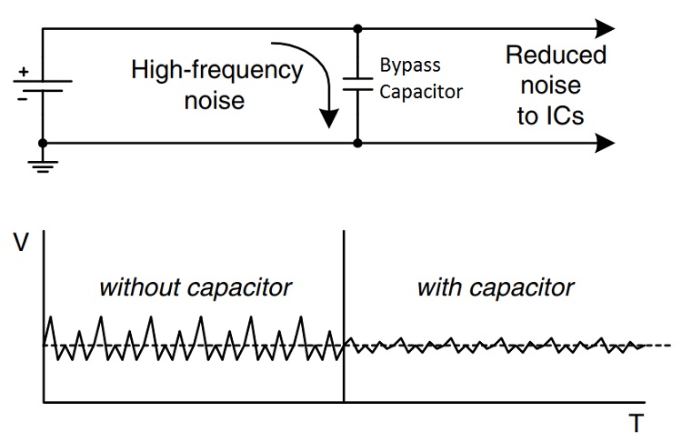
A Bypass Capacitor is usually applied between the VCC and GND pins of an integrated circuit. The Bypass Capacitor eliminates the effect of voltage spikes on the power supply and also reduce the power supply noise.
The name Bypass Capacitor is used as it bypasses the high frequency components of power supply. It is also called as a Decoupling Capacitor as it decouples one part of the circuit from other (usually, the noise from power supply or other ICs is shunted and its effect is reduced on the other part of the circuit).
Bypass Capacitors are generally applied at two locations on a circuit: one at the power supply and other at every active device (analog or digital IC).
The bypass capacitor placed near the power supply eliminate voltage drops in power supply by storing charge and releasing them whenever necessary (usually, when a spike occurs).
Coming to the bypass capacitor placed near VCC and GND pins of an IC will be able to instantaneous current demands of a switching circuit (digital ICs) as the parasitic resistance and inductance delay the instantaneous current delivery.
How Bypass Capacitor Eliminates Power Supply Noise?
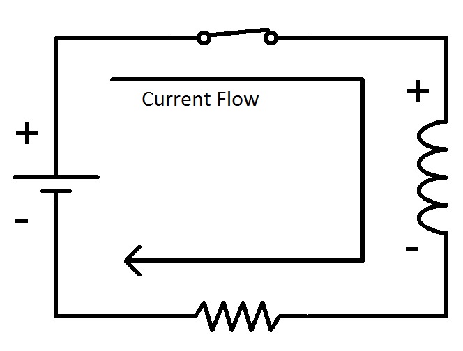
To understand how a bypass capacitor eliminates noise, you need to first understand how a capacitor works in DC and in AC. When a capacitor is connected across a DC power supply, like a battery from example, an electric field is developed across the dielectric with a positive charge on one of the conductors and negative charge on the other.
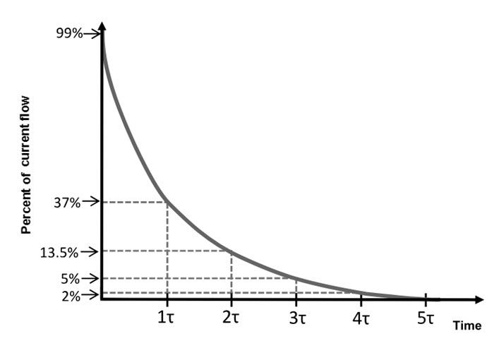
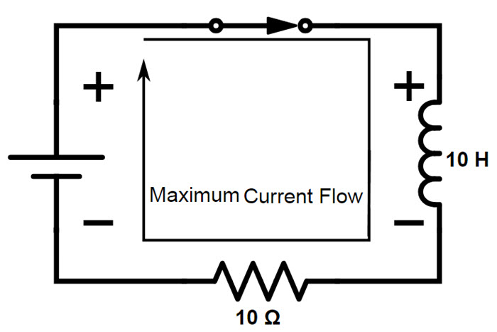
As the capacitor charges, a transient current flows from the supply. But as the charge on the capacitor reaches its maximum (determined by Q = CV), the electric field between the conducting plates of the capacitor nullifies the electric field of the power supply and no more charges flow through capacitor.
Hence, in a DC Circuit, the capacitor charges to the supply voltage and blocks the flow of any current through it.
When a capacitor is connected across a time varying AC power supply, the current flows with little or no resistance due to charging and discharging cycles.
Keeping this in mind, when a Bypass Capacitor is placed across the power supply, it provides a low resistance path for the noise (which is essentially an alternating signal) from supply to ground. Hence, the bypass capacitor shunts the power supply with the nose signals.
Since DC is blocked by the capacitor, it will pass through the circuits instead of passing through the capacitor to ground. This is the reason; this capacitor is also known as Decoupling Capacitor.
Bypass Capacitor Considerations
A circuit without Bypass Capacitor or improper Bypassing can create severe power disturbances and may lead to circuit failure. Hence, an appropriate Bypass Capacitor must be used in the circuit.
The following are a few considerations that must be taken into account when selecting a Bypass Capacitor.
- Capacitor Type
- Capacitor Placement
- Capacitor Size
- Output Load Effect
Capacitor Type
In high frequency circuits, the lead inductance of the bypass capacitor is an important factor. When switching at high frequencies like > 100MHz, a high frequency noise is generated on the power rails and these harmonics in power supply in combination with high lead inductances will cause the capacitor to act as an open circuit.
This prevents the capacitor to supply the necessary current when needed in order to maintain a stable supply. Hence, when selecting a capacitor for bypassing power supply from internal noise of the device (integrated circuit), a capacitor with low lead inductance must be selected.
MLCC or Multilayer Ceramic Chip Capacitors are the preferred choice for bypassing power supply.
Capacitor Placement
The placement of a Bypass Capacitor is very simple. Generally, a Bypass Capacitor is placed as close as possible to the power pin of the device. If the distance increases, the extra tack on the PCB can translate into a series inductor and a series resistor, which lowers the useful bandwidth of the capacitor.
Hence, longer PCB traces between the power pin and the bypass capacitor increases inductance and defeats the purpose of introducing the bypass capacitor in the first place.
Capacitor Size
The size of a bypass capacitor is crucial in determining the ability of the capacitor to supply instantaneous current to the device when needed. There are two things to be considered when determining the size of a capacitor.
- The amount of current required when switching a pin from low to high
- Maximum Pulse Slew Rate to calculate the maximum current of a capacitor
Output Load Effect
If the output load is purely resistive, then the frequency doesn’t affect the rising and falling times of the output. However, if the output load is capacitive, an increase in frequency will cause higher transient current and oscillations in the supply.
Role of Bypass Capacitor in Amplifiers
The following image shows the circuit diagram of a voltage divider biased Amplifier. Resistors R1, R2, RC and RE help the transistor to bias with Q point approximately at the middle of the load line. The resistor RE adds stability to the Q point.
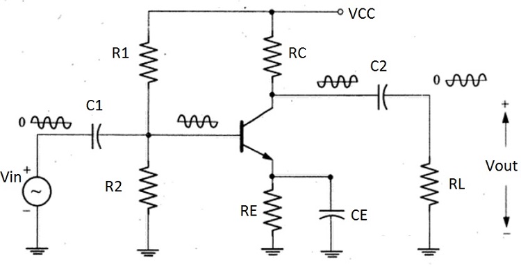
There are two coupling capacitors C1 and C2 at input and output respectively. C1 couples the alternating signal source to the base of the transistor while C2 couples the amplifies signal to the load.
But the device of discussion is the Bypass Capacitor CE. The magnitude of the emitter current is large due to amplification of the ac signal. If there is no bypass capacitor, the large ac emitter current flows through the emitter resistor RE with a large ac voltage drop across RE.
This results in a small ac base current as the voltage drop across the RE subtracts from Vin. Hence, the output voltage decreases and the voltage gain reduces drastically.
We need to provide a low impedance path for the ac emitter current to flow from emitter to ground to prevent a loss of voltage gain. This can be achieved by connecting a capacitor between emitter and ground and this acts as a Bypass Capacitor for bypassing ac emitter current.
Where Bypass Capacitors are used?
Almost all analog and digital devices use bypass capacitors. In both these devices, a bypass capacitor, usually a capacitor or value 0.1µF, is placed very closely to the power pins. Power supply sources also use bypass capacitors and they are usually the larger 10µF capacitors.
The value of bypass capacitor is dependent on the device i.e. in case of power supplies it is between 10µF to 100µF and in case of ICs, it is usually 0.1µF or determined by the frequency of operation.
If the bandwidth of the device is approximately 1MHz, a 1µF bypass capacitor is used. If the bandwidth is approximately 10MHz or above, a 0.1µF capacitor is used.
In some applications, a network of bypass capacitors in parallel is used to filter a wide range of frequencies.
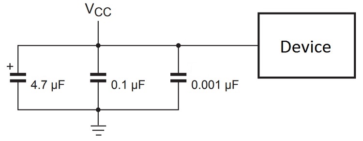
Every active device in a circuit must have a bypass capacitor placed close to the power supply pin. In case there are multiple bypass capacitors, the smaller capacity capacitor must be placed close to the device.
In analog circuits, a bypass capacitor generally redirects the high frequency components on the power supply to ground. Otherwise, these signals would enter into the sensitive analog IC through the power supply pin. If a bypass capacitor is not used in an analog circuit, there is a good chance that noise is introduced into the signal path.
The use of bypass capacitors in Digital circuits with microprocessor and controllers is slightly different. The major function of bypass capacitors in digital circuits is to act as charge reservoirs.
In digital circuits, where the logic gates are switched at high frequency, there is requirement for a large current during the switching. The parasitic resistance and inductance will not allow sudden flow of huge current that is required in the switching process.
Hence, a Bypass, which is placed as close to the power pin as possible to reduce parasitic inductance, will provide the instantaneous current before the power supply could kick-in.
Applications of Bypass Capacitors
The main purpose of a bypass capacitor is to shunt the undesirable high frequency components of a power supply while passing the desirable DC. The following are the three main areas of application of Bypass Capacitors.
Compensate Current Demands
Bypass capacitors are used to provide the necessary current when demanded. For example, the drive current to a loudspeaker from an amplifier varies according to the signal and the current demands of the amplifier’s output are dependent on the loudness of the signal.
Such varying current at the output causes a varying current drawn from the supply. These variations in the power can cause fluctuations that may be coupled to the signal line as noise through the power supply.
Bypass Capacitors can be helpful in reducing the fluctuations by acting as temporary current sources.
Power Supply Filters
In power supplies, large bypass capacitors usually 100µF or 1000µF or more, are used to filter the ripples of the rectified sine wave.
Digital Systems
In digital circuits, a bypass capacitor is used between VCC and GND pins of all the IC. This helps in maintaining a stable power supply within the recommended range of the IC and also to eliminate high frequency signals from entering the power supply. Additionally, they also act as instantaneous current providers in fast switching circuits.
The post What is a Bypass Capacitor? Tutorial | Applications appeared first on Electronics Hub.
from Electronics Hub http://bit.ly/2Kemgq7
 Here is a simple DC motor speed controller circuit that can be configured to control the sweep rate of automobiles’ windscreen wiper. The circuit comprises a timer NE555 (IC1), medium-power driver transistor BD239 (T1), high-power switching transistor BD249 (T2) and a few other discrete components. It is configured for automobile usage with negative terminal of […]
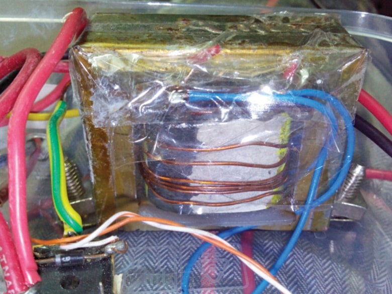 This circuit breaker employs a single operational amplifier (op-amp) and yet has a wide range and is user-friendly. A circuit breaker is an electrical switch intended to protect an electrical circuit or device from damage caused by excess current flow or short-circuit. A basic circuit breaker includes a simple fuse and a normal miniature circuit […]
 AI is becoming a disruptive force that is redefining the modern industry. This article features some exciting applications of AI, along with a glimpse into the future, illustrating how AI will continue to transform industries and our lives. Sophia, an artificial intelligence (AI) humanoid, was in the news recently for becoming the first robot ever […]
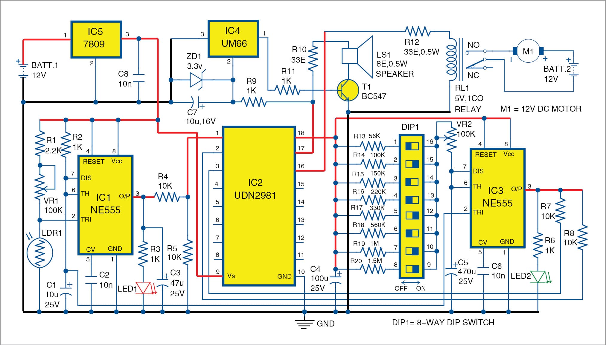 Here is a circuit for automatic plants watering, which can be undertaken every morning without any human effort. A sensor is used to detect ambient light and activate a pump motor to start watering the plants in the morning. You can set the watering time duration as per your requirement. The author’s prototype is shown […]
 In this article we take a look at the various technology trends and interesting solutions we came across while visiting different parts of the globe throughout the year. Every year brings new opportunities to discover new technological inventions that can deliver real-life improvements. Many of the most-talked-about technologies today were discovered decades ago but have […]
 Virtual and augmented reality technologies are coming of age and finding many valuable real-world applications. Once upon a time our physical and digital worlds were quite separate, but technological advances are enabling digital worlds to become real enough to merge with the real world. Technologies such as virtual reality (VR) and augmented reality (AR) have […]
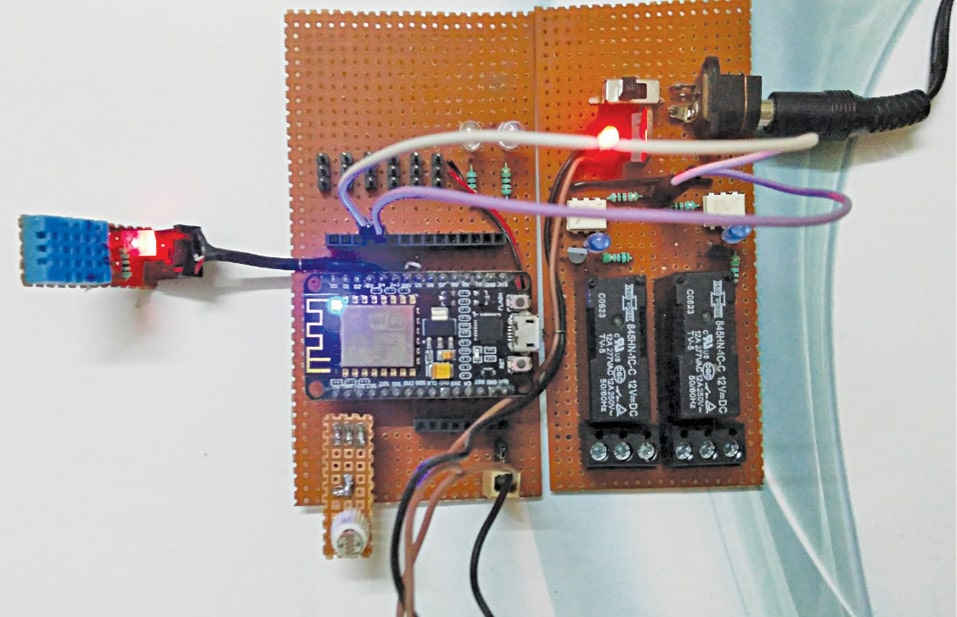 This home automation system can measure temperature, relative humidity, light intensity and control two electrical equipment on Cayenne IoT (Internet of Things) platform. The two electrical equipment can be a light bulb and a ceiling fan, or any other electrical devices. The author’s prototype is shown in Fig. 1. Basic IoT components An IoT system […]
 A power supply converts AC voltage into regulated DC voltage. Read on to find out how to select the best power supply for an electronic device. A power supply for an electronic equipment is a circuit that converts AC voltage into regulated DC voltage. An electronic device does not normally use electric energy in the […]
 Dronecode Visit: Click here Full version: Free (BSD licence) Dronecode software development kit (SDK) is an unmanned aerial vehicle (UAV) program development platform created under the open source Dronecode project. It allows users to connect up to 255 PX4-based unmanned aircraft systems (UASes) to provide movement control and fetch telemetry data. It runs on different platforms […]
 In this video, the presenter is going to show you how he has used Raspberry Pi and a 3.5 inches display unit to create his own mini Pocket Personal computer. It is easy to make and take very less time constructing. Courtesy: The Wrench
 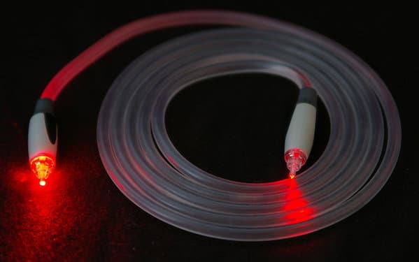 In this era of communication and connectivity, optical-fibre sensors find many applications, some of which are discussed in this article. For ages, sensors have been used in hazardous environments. These sensors often contain electronic components. In the past, it was a challenge for engineers to make sensors work at extremely high temperatures, such as in […]
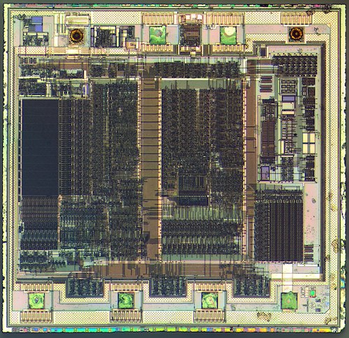 This article highlights common errors in 8-bit instruction sets, and introduces a novel architecture for decimal conversion instructions, especially in 8051, 8086, 8085 and PIC microcontrollers (MCUs). Statistical analysis of different methodologies has revealed that decimal conversion instructions in microprocessors and MCUs do not offer an error-free process. Bugs can be common for the above-mentioned […]

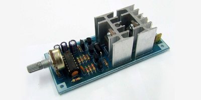
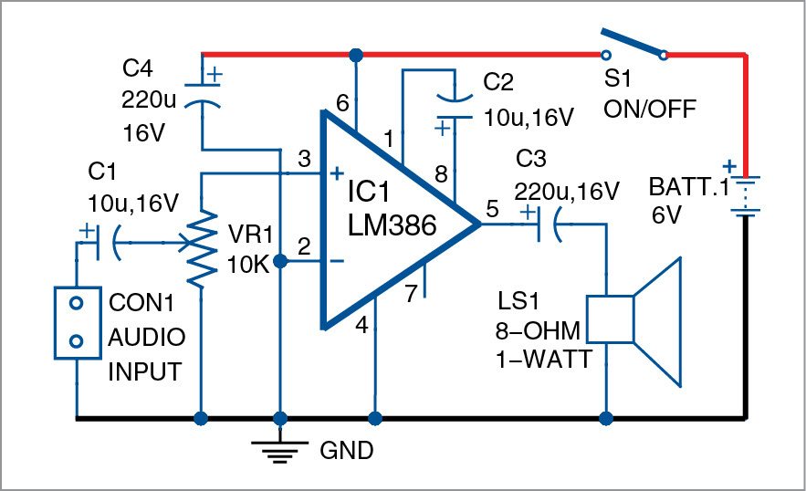 Here is a simple LM386 based audio amplifier circuit with the author’s prototype shown below. LM386 based audio amplifier: circuit and working Circuit diagram of the LM386 based audio amplifier is shown in Fig. 2. It is built around popular amplifier LM386 (IC1), an 8-ohm, one-watt speaker (LS1), four capacitors and a few other components. […]
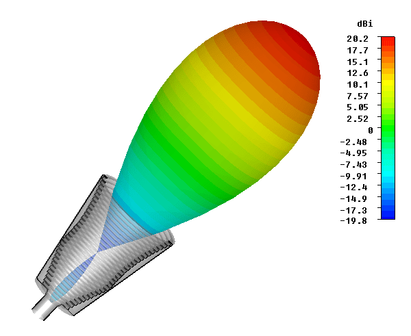 RF antennas or aerials do not radiate equally in all directions. It is found that any realisable RF antenna design will radiate more in some directions than others. The actual pattern is dependent upon the type of antenna design, its size, the environment and a variety of other factors. This directional pattern can be used […]
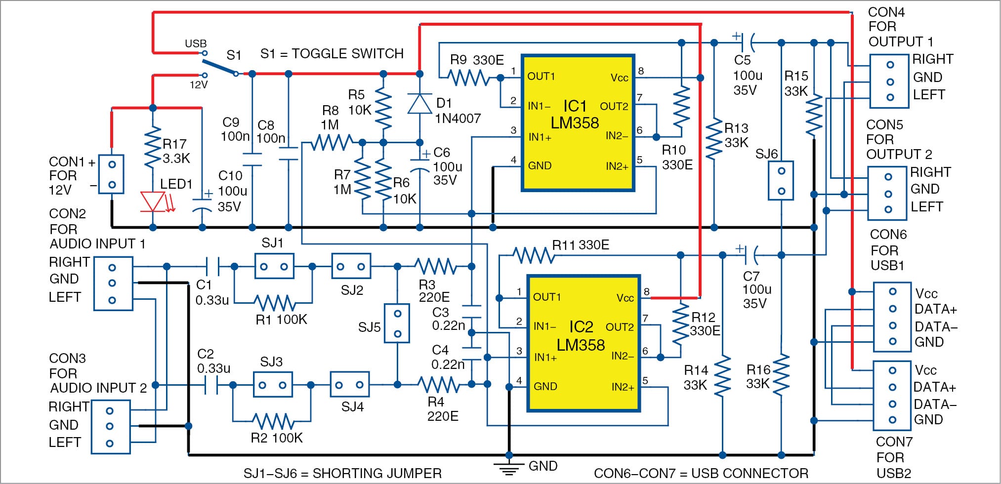 This article presents a simple, low-cost stereo headphones buffer using two LM358 operational amplifiers (op-amps). It is used to connect the headphones to line outputs capable of driving loads up to 600-ohm. The circuit has a high input impedance, low quiescent current and large voltage operating range. Power can be taken either from a USB […]
 Electronic devices, microwaves and other household devices rely on PCB technology to stay in working condition. Lifetime and performance of a PCB board depend on the choice of circuit board material. To select the right circuit board material, it is important to examine the materials available for different board categories. There are different properties and […]
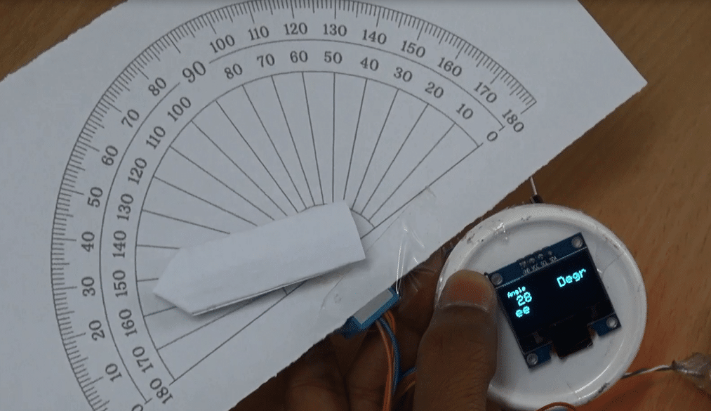 A compass and a protractor are two of the most basic tools used in geometry. For mathematics and engineering students, these tools are a must. But sometimes it is difficult to get accurate angle measurement for certain structures and geometrical shapes using these traditional tools. So, I thought of developing a digital compass to make […]
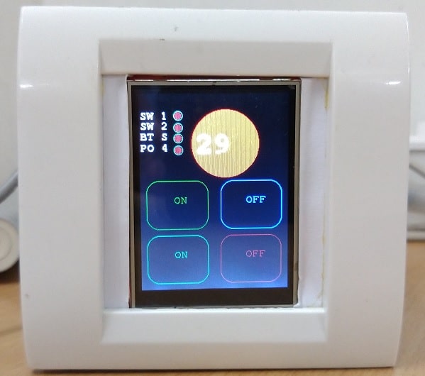 If you are still using the traditional switches, then I’m sorry to say this but they are outdated now. Moreover, these traditional switches have mechanical moving parts which get damaged on continuous use. Nowadays, old switch boards are getting replaced by modern touch switches that not only enhance the look of our homes but are […]
 Improvements to recommendation systems is a low-hanging fruit that would not only ensure that customers have a high repeat rate but also improve customer experience. Recommendation systems are one of the primary ways in which e-commerce websites tend to generate repeat purchases, that is, getting a purchase from an already registered customer. Repeat purchase is […]
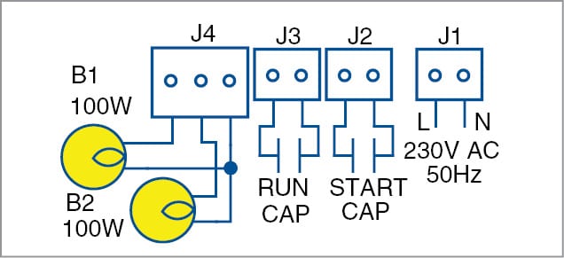 Presented here is a submersible pump starter circuit using electronic overload relay, solid-state relay and adjustable startup delay. A submersible pump is a type of centrifugal pump designed to function with the pump and the motor completely submerged in the water. The motor is sealed in such a way that it prevents any ingress of […]
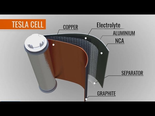 In this video, the presenter is going to share with you the working principle of a Li-ion cell and how it is used in Electric cars. He is going to also explain why Li-ion cell technology is superior to other conventional vehicle technology like combustion engines, induction motors etc. Courtesy: Learn Engineering
 In simple terms, nanotechnology is the part of science that deals with the control of matter with dimensions smaller than 100 nanometres, and can go down to atomic and molecular scales. The study and manipulation of matter, particles and structures on the nanometer scale is referred to as nanoscience. Nanotechnology is the application of nanoscience […]
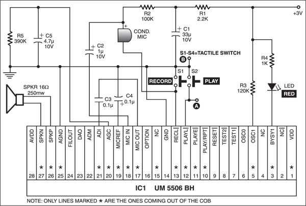 This alarm plays your prerecorded voice message. It is built around the readily available quartz clock. Take the buzzer out of the quartz clock and connect its positive terminal to pin 1 and negative terminal to pin 2 of optocoupler IC MCT2E (IC2). Pin 4 of IC2 is grounded and pin 5 is connected to […]
 This simple telephone caller identification display can be very useful for bikers. While riding a bike or any two-wheeler, the cellphone is usually kept in a pocket. When you receive a phone call on your cellphone, you do not know who is calling unless you look at the screen. And sometimes you may not even […]