Tony Armstrong of Analog Devices, Inc., shares his thoughts in an interview with AAC on smart risks, thinking big, and the importance of reading data sheets.
from All About Circuits News https://ift.tt/2FGUNbm
Sunday, 31 March 2019
Friday, 29 March 2019
ROHM Announces New Automotive-Grade SIC MOSFET Series
The AEC-Q101-qualified MOSFETs utilize a trench gate structure and feature 650V or 1200V breakdown voltages.
from All About Circuits News https://ift.tt/2YJ53Zo
from All About Circuits News https://ift.tt/2YJ53Zo
Introduction to Reliability in Electronics: Tools and Metrics for Anticipating Device Failure
Reliability engineering estimates device lifetimes and failure rates to determine what will fail and when.
from All About Circuits Technical Articles https://ift.tt/2CHhdZc
from All About Circuits Technical Articles https://ift.tt/2CHhdZc
Loop-Based Anti-Theft Alarm
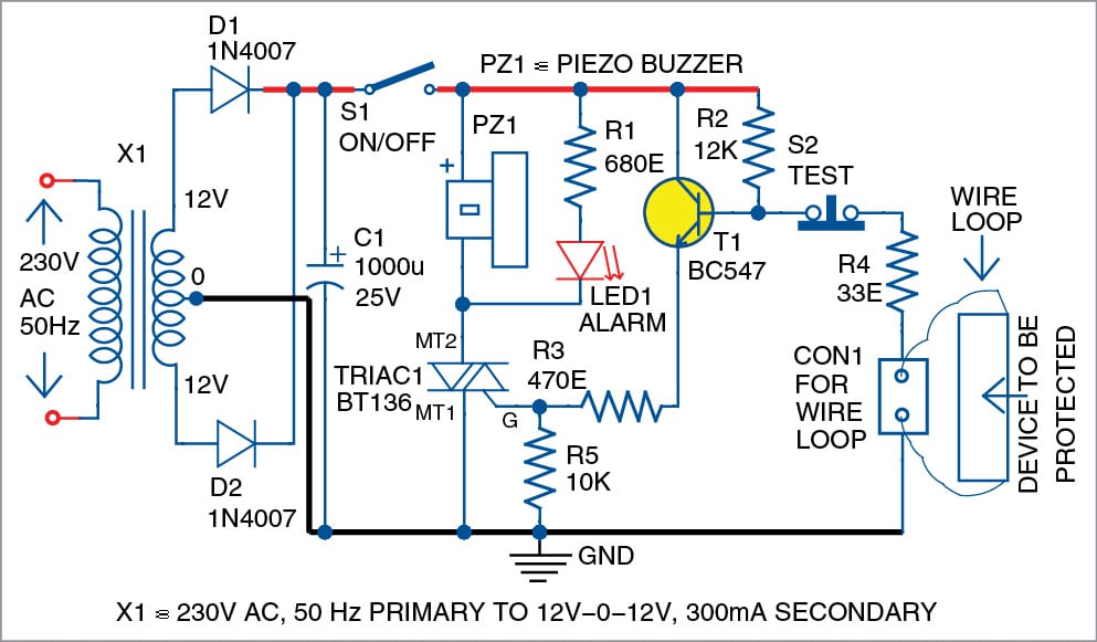 Presented here is a triac-based anti-theft alarm circuit using a simple wire loop as sensor. It can be used to protect any device against theft, or as a door opening alarm. Make sure that when the device moves, or the door opens, the sensing loop breaks, too. The author’s prototype is shown in Fig. 1. […]
The post Loop-Based Anti-Theft Alarm appeared first on Electronics For You.
from Electronics For You https://ift.tt/2JOEoH8
Murata Features Low-Power, High Efficiency With New Components
New Wi-Fi/Bluetooth combo module and buck regulator promise small form factors along with high efficiency.
from All About Circuits News https://ift.tt/2FJhcGc
from All About Circuits News https://ift.tt/2FJhcGc
Thursday, 28 March 2019
How to Choose the Right Microcontroller for Your Application
This article continues the Introduction to Microcontrollers series with a discussion of the most important things to consider when you’re trying to find the best MCU for your next project.
from All About Circuits Technical Articles https://ift.tt/2TZTMVE
from All About Circuits Technical Articles https://ift.tt/2TZTMVE
UnitedSiC Announces SiC JFET Family for Low Power AC-DC Flyback Converters
These normally-ON devices are well-suited to form the nucleus of cascode-based 20-100 Watt flyback products.
from All About Circuits News https://ift.tt/2Wrc3bb
from All About Circuits News https://ift.tt/2Wrc3bb
SENSORS: How To Check Food Adulteration
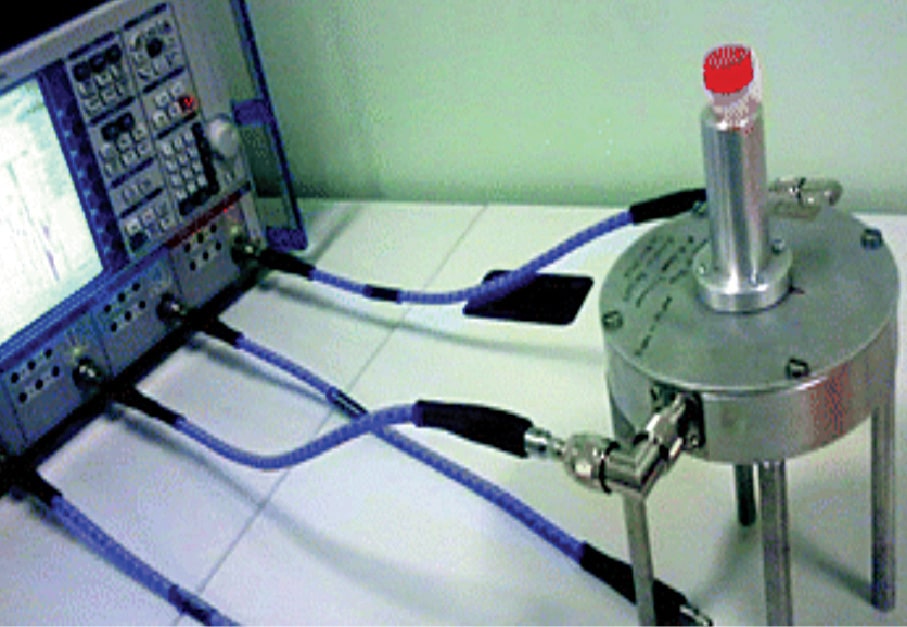 Nowadays, adulteration is being done in sophisticated ways that demand cutting-edge research for the detection of adulterants. Due to changing social values where companies are focussing on reaping rich profits, adulteration is prevalent in almost all commodities such as food items, fuel, cloths and construction materials. Adulteration has reached alarming levels and is, hence, making […]
The post SENSORS: How To Check Food Adulteration appeared first on Electronics For You.
from Electronics For You https://ift.tt/2YvUCbl
Wednesday, 27 March 2019
Popular Toshiba Flash Memory Platform Now Qualified for Automotive Applications
The new devices adhere to the tough AEC-Q100 Grade2 standard and range from 32GB to 256GB capacity.
from All About Circuits News https://ift.tt/2UUSPue
from All About Circuits News https://ift.tt/2UUSPue
New Renesas Power Modules Claim Highest Density at 10A and 15A, Leverage New Packaging and PMBus
At APEC 2019, Renesas highlighted new PMBus DC-DC power modules.
from All About Circuits News https://ift.tt/2YuNpID
from All About Circuits News https://ift.tt/2YuNpID
Half & Full Wave Rectifier | Rectifier Basics
 Power conversion is very common with today’s electronics. We constantly switch from AC to DC and vice-versa. The common source of AC is the power supply whereas, batteries are used for DC power as and when required. The conversion from AC to DC is, however, an easier way instead of buying a new battery every […]
The post Half & Full Wave Rectifier | Rectifier Basics appeared first on Electronics For You.
from Electronics For You https://ift.tt/2V4k5qt
Capacitive Reactance
 A capacitor by structure consists of two conductors separated by an insulator that is often referred to as a dielectric. It is often used to filter out DC component in electronics circuits as it only allows DC component to pass through. Meaning, for very low frequencies (high DC component low AC component), the capacitor acts […]
The post Capacitive Reactance appeared first on Electronics For You.
from Electronics For You https://ift.tt/2U0R7uP
Tuesday, 26 March 2019
Innovative Isolated ICs from Silicon Labs Promise Precision and Stability
The newly-announced Si89xx product family provides voltage, current, and package options.
from All About Circuits News https://ift.tt/2uwcw02
from All About Circuits News https://ift.tt/2uwcw02
Automatic Infrared Faucet Controller
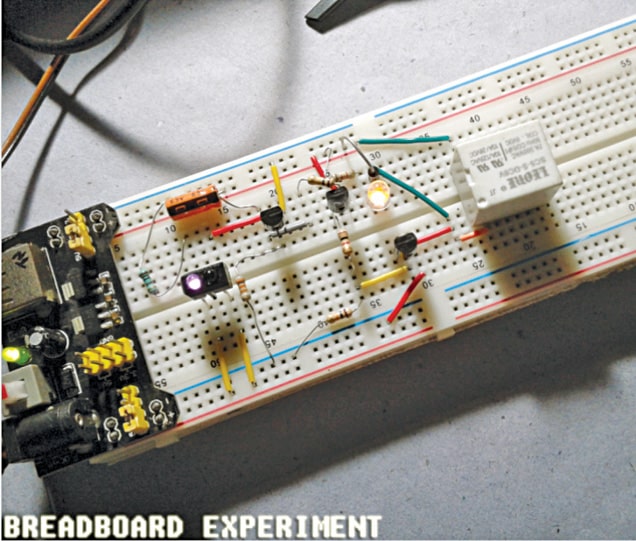 Described here is an easy-to-use circuit of an automatic infrared (IR) faucet controller suitable for hand hygiene and water conservation at homes, hospitals and offices. With this compact controller you can turn on and off a faucet automatically, preventing water wastage and saving energy costs. The core part of the faucet controller is an electronic […]
The post Automatic Infrared Faucet Controller appeared first on Electronics For You.
from Electronics For You https://ift.tt/2UYgnyy
Monday, 25 March 2019
What Is a Microcontroller? The Defining Characteristics and Architecture of a Common Component
In this article we’ll look at the defining characteristics of these extremely popular ICs, and then we’ll explore the internal architecture.
from All About Circuits News https://ift.tt/2FqrVUy
from All About Circuits News https://ift.tt/2FqrVUy
TDK Claims World’s Smallest Point-of-Load DC-DC Converter
Tiny DC-DC converters with highest power density point-of-load, work with a wide variety of applications.
from All About Circuits News https://ift.tt/2OmY2se
from All About Circuits News https://ift.tt/2OmY2se
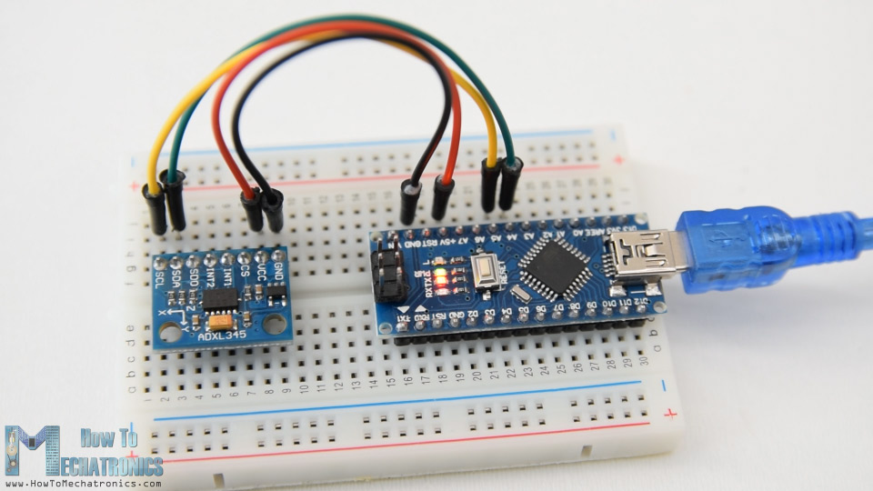
How To Track Orientation with Arduino and ADXL345 Accelerometer
In this tutorial we will learn how to measure angle and track orientation using the Arduino and the ADXL345 Accelerometer sensor. You can watch the following video or read the written tutorial below for more details.
Overview
First, I will explain how the sensor work and how to read the data from it, and then using the Processing development environment, we will make a 3D visualization of the accelerometer orientation.
How ADXL345 Accelerometer Works
To begin with, let’s take a look how the ADXL345 sensor works. This is a 3-axis accelerometer which can measure both static and dynamic forces of acceleration. The earth gravitational force is a typical example of static force, while dynamic forces can be caused by vibrations, movements and so on.
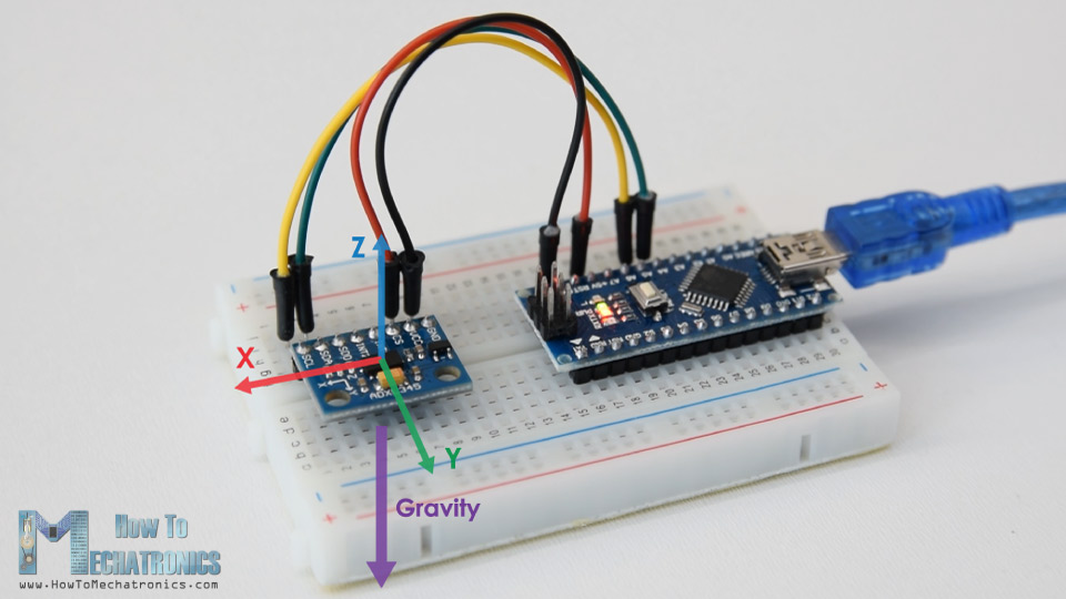
The unit of measurement for acceleration is meter per second squared (m/s^2). However, accelerometer sensors usually express the measurements in “g” or gravity. One “g” is the value of the earth gravitational force which is equal to 9.8 meters per second squared.
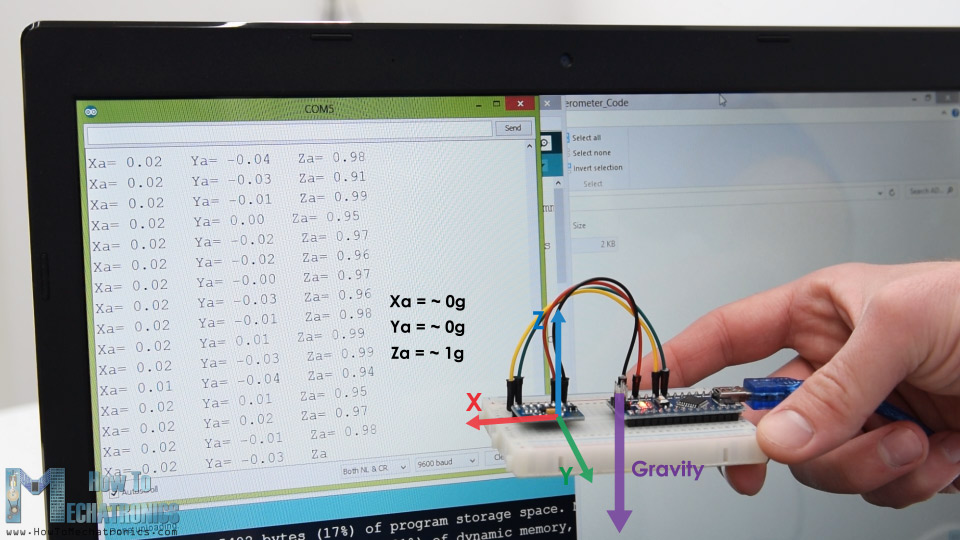
So, if we have an accelerometer positioned flat, with its Z-axis pointing upwards, opposite to the gravitational force, the Z-axis output of the sensor will be 1g. On the other hand, the X and Y outputs will be zero, because the gravitational force is perpendicular to these axes and doesn’t affect them at all.
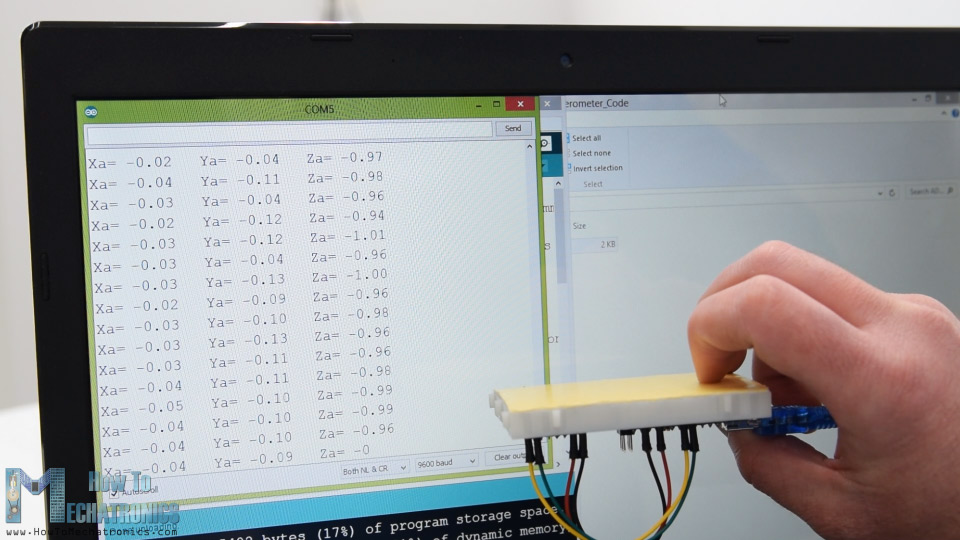
If we flip the sensor upside down, then the Z-axis output will be -1 g. This means that the outputs of the sensor due to its orientation to gravity can vary from -1g to +1g.
So according to this data and using some trigonometry math, we can calculate the angle at which the sensor is positioned.
How to Read ADXL345 Accelerometer Data with Arduino
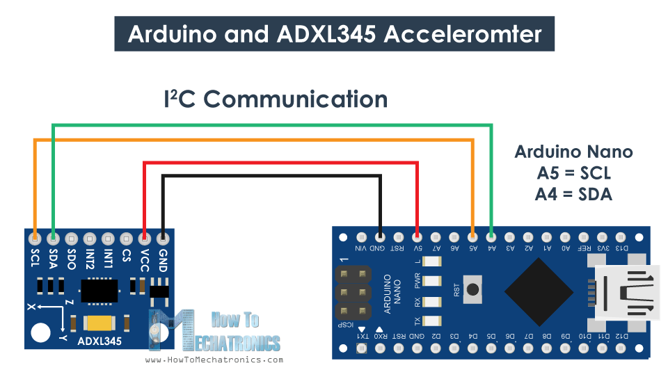
Ok, now let’s see how we can read the ADXL345 accelerometer data using the Arduino. This sensor uses the I2C protocol for communication with the Arduino so we need only two wires for connecting it, plus the two wires for powering it.
You can get the components needed for this Arduino Tutorial from the links below:
- ADXL345 Accelerometer ………………. Amazon / Banggood
- Arduino Board …………………………….. Amazon / Banggood
- Breadboard and Jump Wires ………… Amazon / Banggood
*Please note: These are affiliate links. I may make a commission if you buy the components through these links. I would appreciate your support in this way!

ADXL345 Accelerometer Arduino Code
Here’s the Arduino code fo reading the ADXL345 accelerometer data.
/*
Arduino and ADXL345 Accelerometer Tutorial
by Dejan, https://howtomechatronics.com
*/
#include <Wire.h> // Wire library - used for I2C communication
int ADXL345 = 0x53; // The ADXL345 sensor I2C address
float X_out, Y_out, Z_out; // Outputs
void setup() {
Serial.begin(9600); // Initiate serial communication for printing the results on the Serial monitor
Wire.begin(); // Initiate the Wire library
// Set ADXL345 in measuring mode
Wire.beginTransmission(ADXL345); // Start communicating with the device
Wire.write(0x2D); // Access/ talk to POWER_CTL Register - 0x2D
// Enable measurement
Wire.write(8); // (8dec -> 0000 1000 binary) Bit D3 High for measuring enable
Wire.endTransmission();
delay(10);
}
void loop() {
// === Read acceleromter data === //
Wire.beginTransmission(ADXL345);
Wire.write(0x32); // Start with register 0x32 (ACCEL_XOUT_H)
Wire.endTransmission(false);
Wire.requestFrom(ADXL345, 6, true); // Read 6 registers total, each axis value is stored in 2 registers
X_out = ( Wire.read()| Wire.read() << 8); // X-axis value
X_out = X_out/256; //For a range of +-2g, we need to divide the raw values by 256, according to the datasheet
Y_out = ( Wire.read()| Wire.read() << 8); // Y-axis value
Y_out = Y_out/256;
Z_out = ( Wire.read()| Wire.read() << 8); // Z-axis value
Z_out = Z_out/256;
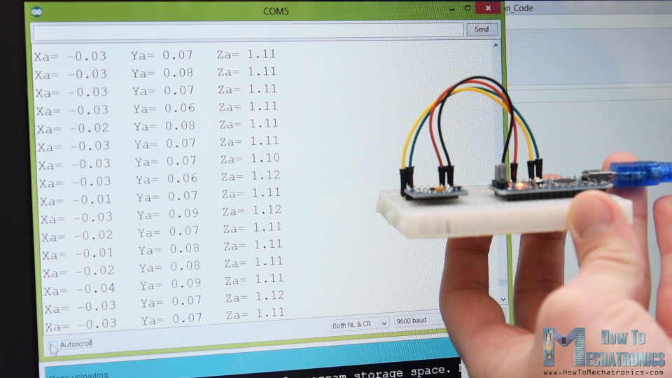
Serial.print("Xa= ");
Serial.print(X_out);
Serial.print(" Ya= ");
Serial.print(Y_out);
Serial.print(" Za= ");
Serial.println(Z_out);
}
Description: So first we need to include the Wire.h library which is used for the I2C communication. If you want to learn more on how the I2C communication works and how to use it with Arduino you can check my other detailed tutorial for it.
Each device that uses the I2C communication has a unique I2C address, and this address can be found in the datasheet of the sensor (ADXL345 Datasheet). So, once we define the address and the variables for the three outputs, in the setup section, first, we need to initialize the wire library and then set the accelerometer in measuring mode. In order to do that, if we take a look at the datasheet again, we can see that we need to set the bit D3 of the POWER_CTL register HIGH.
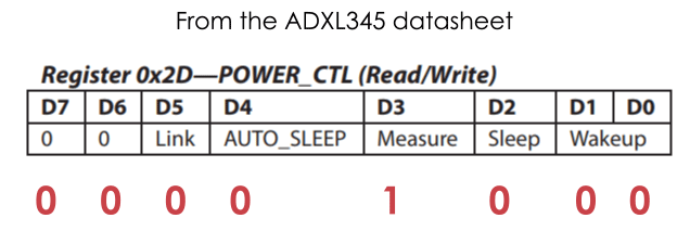
So, using the beginTransmission() function we start the communication, then using the write() function we tell which register we want to access, and again using the write() function we set the D3 bit HIGH, by writing the number 8 in decimal which correspond to setting the bit D3 HIGH.
// Set ADXL345 in measuring mode
  Wire.beginTransmission(ADXL345); // Start communicating with the device
  Wire.write(0x2D); // Access/ talk to POWER_CTL Register - 0x2D
  // Enable measurement
  Wire.write(8); // (8dec -> 0000 1000 binary) Bit D3 High for measuring enable
  Wire.endTransmission();
In the loop section now we read the data from the sensor. The data for each axis is stored in two bytes or registers. We can see the addresses of these registers from the datasheet.
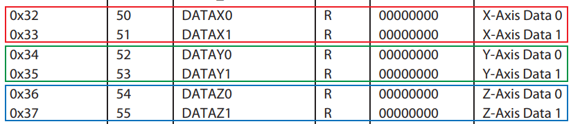
In order to read them all, we start with the first register, and the using the requestionFrom() function we ask to read the 6 registers. Then using the read() function, we read the data from each register, and because the outputs are twos complements we combine them appropriately to get the correct values.
// === Read acceleromter data === //
  Wire.beginTransmission(ADXL345);
  Wire.write(0x32); // Start with register 0x32 (ACCEL_XOUT_H)
  Wire.endTransmission(false);
  Wire.requestFrom(ADXL345, 6, true); // Read 6 registers total, each axis value is stored in 2 registers
  X_out = ( Wire.read()| Wire.read() << 8); // X-axis value
  X_out = X_out/256; //For a range of +-2g, we need to divide the raw values by 256, according to the datasheet
  Y_out = ( Wire.read()| Wire.read() << 8); // Y-axis value
  Y_out = Y_out/256;
  Z_out = ( Wire.read()| Wire.read() << 8); // Z-axis value
  Z_out = Z_out/256;
The output values from the sensor actually depend on the selected sensitivity, which can vary from +- 2g to +-16g. The default sensitivity is +-2g so that’s why we need to divide the output by 256 in order to get values from -1 to +1g. The 256 LSB/g means that we have 256 counts per g.
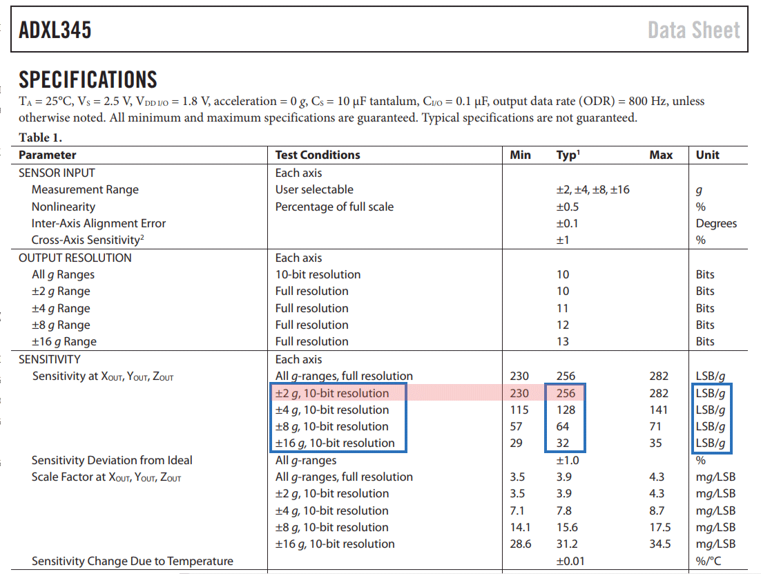
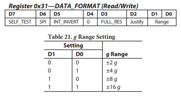
Depending on the application we can select the appropriate sensitivity. In this case, for tracking orientation, +-2g sensitivity is fine, but for application where we need to sense higher acceleration force from like sudden movements, shocks and so on, we can choose some of the other sensitivity ranges using the DATA_FORMAT register and its D1 and D0 bits.
ADXL345 Acceleromter Calibration
Nevertheless, once we read the data, we can simply print it on the serial monitor to check whether the values are as expected. In my case, the values I was getting were not exactly as they should be, especially the Z-axis which had a noticeable error of 0.1g.
To solve this issue, we need to calibrate the accelerometer using the 3 offset calibration registers, and here’s how we can do that. So, we need to position the sensor flat, and print the RAW values without dividing them by 256.

From here now we can notice the how much the outputs are off, in my case, the Z output was around 283. That’s difference of 27 in positive. Now we need to divide this value by 4, and that will give use the number that we need to write to the Z-axis offset register. If we upload the code now, the Z-axis output will be exactly 256, or 1g as it should be.
// This code goes in the SETUP section
// Off-set Calibration
  //X-axis
  Wire.beginTransmission(ADXL345);
  Wire.write(0x1E);  // X-axis offset register
  Wire.write(1);
  Wire.endTransmission();
  delay(10);
  //Y-axis
  Wire.beginTransmission(ADXL345);
  Wire.write(0x1F); // Y-axis offset register
  Wire.write(-2);
  Wire.endTransmission();
  delay(10);

  //Z-axis
  Wire.beginTransmission(ADXL345);
  Wire.write(0x20); // Z-axis offset register
  Wire.write(-7);
  Wire.endTransmission();
  delay(10);
If needed we should calibrate the other axis using the same method. And just a quick note that this calibration is not permanently written to the registers. We need to do write these values to the registers at each power up of the sensor.
Once we are done with the calibration, we can now finally calculate the Roll and Pitch, or the rotation around the X-axis and the rotation around the Y axis in degrees, using these two formulas.
// Calculate Roll and Pitch (rotation around X-axis, rotation around Y-axis)
  roll = atan(Y_out / sqrt(pow(X_out, 2) + pow(Z_out, 2))) * 180 / PI;
  pitch = atan(-1 * X_out / sqrt(pow(Y_out, 2) + pow(Z_out, 2))) * 180 / PI;
For more details how these formulas work, you can check this Freescale Semiconductor application note.
Arduino and ADXL345 Accelerometer Orientation Tracking – 3D Visualization
Ok, let’s make the accelerometer 3D visualization example now.
![]()
So, we are using the same code, which sends the Roll and Pitch values through the serial port. Here’s the complete Arduino code:
/*
    Arduino and ADXL345 Accelerometer - 3D Visualization Example
     by Dejan, https://howtomechatronics.com
*/
#include <Wire.h>  // Wire library - used for I2C communication

int ADXL345 = 0x53; // The ADXL345 sensor I2C address

float X_out, Y_out, Z_out;  // Outputs
float roll,pitch,rollF,pitchF=0;

void setup() {
  Serial.begin(9600); // Initiate serial communication for printing the results on the Serial monitor

  Wire.begin(); // Initiate the Wire library
  // Set ADXL345 in measuring mode
  Wire.beginTransmission(ADXL345); // Start communicating with the device
  Wire.write(0x2D); // Access/ talk to POWER_CTL Register - 0x2D
  // Enable measurement
  Wire.write(8); // Bit D3 High for measuring enable (8dec -> 0000 1000 binary)
  Wire.endTransmission();
  delay(10);

  //Off-set Calibration
  //X-axis
  Wire.beginTransmission(ADXL345);
  Wire.write(0x1E);
  Wire.write(1);
  Wire.endTransmission();
  delay(10);
  //Y-axis
  Wire.beginTransmission(ADXL345);
  Wire.write(0x1F);
  Wire.write(-2);
  Wire.endTransmission();
  delay(10);

  //Z-axis
  Wire.beginTransmission(ADXL345);
  Wire.write(0x20);
  Wire.write(-9);
  Wire.endTransmission();
  delay(10);
}

void loop() {
  // === Read acceleromter data === //
  Wire.beginTransmission(ADXL345);
  Wire.write(0x32); // Start with register 0x32 (ACCEL_XOUT_H)
  Wire.endTransmission(false);
  Wire.requestFrom(ADXL345, 6, true); // Read 6 registers total, each axis value is stored in 2 registers
  X_out = ( Wire.read() | Wire.read() << 8); // X-axis value
  X_out = X_out / 256; //For a range of +-2g, we need to divide the raw values by 256, according to the datasheet
  Y_out = ( Wire.read() | Wire.read() << 8); // Y-axis value
  Y_out = Y_out / 256;
  Z_out = ( Wire.read() | Wire.read() << 8); // Z-axis value
  Z_out = Z_out / 256;

  // Calculate Roll and Pitch (rotation around X-axis, rotation around Y-axis)
  roll = atan(Y_out / sqrt(pow(X_out, 2) + pow(Z_out, 2))) * 180 / PI;
  pitch = atan(-1 * X_out / sqrt(pow(Y_out, 2) + pow(Z_out, 2))) * 180 / PI;

  // Low-pass filter
  rollF = 0.94 * rollF + 0.06 * roll;
  pitchF = 0.94 * pitchF + 0.06 * pitch;

  Serial.print(rollF);
  Serial.print("/");
  Serial.println(pitchF);
}
Now in the Processing development environment we need to receive these values and use them to rotate the 3D object that we will create. Here’s the complete Processing code:
/*
    Arduino and ADXL345 Accelerometer - 3D Visualization Example
     by Dejan, https://howtomechatronics.com
*/

import processing.serial.*;
import java.awt.event.KeyEvent;
import java.io.IOException;

Serial myPort;

String data="";
float roll, pitch;

void setup() {
  size (960, 640, P3D);
  myPort = new Serial(this, "COM8", 9600); // starts the serial communication
  myPort.bufferUntil('\n');
}

void draw() {
  translate(width/2, height/2, 0);
  background(33);
  textSize(22);
  text("Roll: " + int(roll) + "     Pitch: " + int(pitch), -100, 265);

  // Rotate the object
  rotateX(radians(roll));
  rotateZ(radians(-pitch));

  // 3D 0bject
  textSize(30);
  fill(0, 76, 153);
  box (386, 40, 200); // Draw box
  textSize(25);
  fill(255, 255, 255);
  text("www.HowToMechatronics.com", -183, 10, 101);

  //delay(10);
  //println("ypr:\t" + angleX + "\t" + angleY); // Print the values to check whether we are getting proper values
}

// Read data from the Serial Port
void serialEvent (Serial myPort) {
  // reads the data from the Serial Port up to the character '.' and puts it into the String variable "data".
  data = myPort.readStringUntil('\n');

  // if you got any bytes other than the linefeed:
  if (data != null) {
    data = trim(data);
    // split the string at "/"
    String items[] = split(data, '/');
    if (items.length > 1) {

      //--- Roll,Pitch in degrees
      roll = float(items[0]);
      pitch = float(items[1]);
    }
  }
}
Description: So here, we need to include the serial library, define the serial port and the baud rate which needs to match we the baud rate of the uploaded Arduino sketch. Then we read the incoming data and put it into the appropriate roll and pitch variables. In the main draw loop, we use these values to rotate the 3D object, and in this case that’s a simple box with has a particular color and a text on it.
If we run the sketch, the 3D object will appear and it will track the orientation of the accelerometer sensor. We can notice here that the object is actually a bit shaky and that’s because the accelerometer captures not just the gravitational force, but also small forces generated by the movements of our hand. In order to get smoother result, we can use a simple Low-pass filter. Here I implemented such a filter in the Arduino code, which it takes 94% of the previous state and adds 6% of the current state or angle.
// Low-pass filter
  rollF = 0.94 * rollF + 0.06 * roll;
  pitchF = 0.94 * pitchF + 0.06 * pitch;
With this filter, we can notice that the object moves a lot smoother now, but there is also a side effect and that’s slower responsiveness. We can also notice that we are missing the Yaw, or rotation around the Z-axis. Using only the 3-axis accelerometer data we are not able to calculate the Yaw.
In order to do that and improve the overall performance of our orientation tracking sensor, we actually need to include an additional sensor, a gyroscope, and fuse its data with the accelerometer.
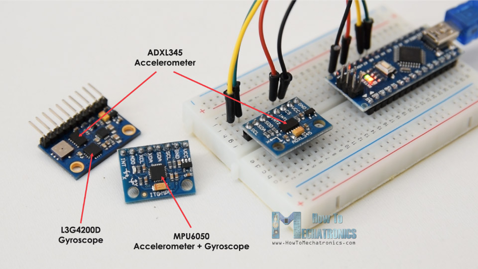
So, we can either use the ADXL345 accelerometer in combination some gyroscope sensor, or use the MPU6050 IMU which has both 3-Axis accelerometer and 3-Axis gyroscope integrated on a single chip. You can find more detailed tutorial on this sensor in my next video.
I hope you enjoyed this tutorial and learned something new. Feel free to ask any question in the comments section below and don’t forget to check my collection of Arduino Projects.
The post How To Track Orientation with Arduino and ADXL345 Accelerometer appeared first on HowToMechatronics.
from HowToMechatronics https://ift.tt/2FztT6f
“Faster, Smaller, Quieter”: Analog Devices Shows Off Silent Switcher 2 Buck Regulator at APEC
A look at the Analog Devices Silent Switcher 2 buck regulator.
from All About Circuits News https://ift.tt/2HIUzDY
from All About Circuits News https://ift.tt/2HIUzDY
How Telecom Is Transforming Rural India
This report shares an overview of the potential of the telecom industry in rural India and the various technologies that can help drive the initiatives. India has no dearth of technological and business innovations for rural areas. However, telecom policies and scams have created a negative impact on the growth of this sector in rural […]
The post How Telecom Is Transforming Rural India appeared first on Electronics For You.
from Electronics For You https://ift.tt/2UTuEMX
TDA11105PS/N3/3 COLOR TV CHROMA IC DATA SHEET AND PINOUT PDF
TDA11105PS/N3/3 PIN DESCRIPTION

1 IFVO
2 VP2
3 VCC AUDIO
4 PLLIF
5GND2
6 DECSDEM
7 FMDEMOUT
8 EHTO
9 AGC
10 IREF
11CSC
12IF IN2
13 IF IN 1
14 VDRA
15 VDRB
16 AVLEW
17 DECBG
18 SECPLL
19 GNG1
20 PHL1FL
21 PHL2FL
22 VP1
23 DECDIG
24 XTALOUT
25 XTALIN
26 IR
27 MUTE
28 TILT
29 KEY
30 BAND2
31 BAND1
32 TUNNING
33 VDDP
34 SCL
35 SDA
36
37 TV/AV
38 STANDBY
39
40 VDD
41GND5
42 VPE
43 VDDA
44 BOUT
45 GOUT
46 ROUT
47 BLKIN
48 BCLIN
49 PB
50 YS/CVBS
51 PR/C3
52 YOUT
53 YSYNC
54 VP3
55 GND 3
56 HOUT
57 FBISO
58 LSR
59 LSL
60 C2/C3/C4
61 AIN3/IN1R
62 CVBSE/Y2
63 A/N2/N1L
64 CVBS4/Y4

Other ic datas are available in this link
tda11105ps/n3/3 datasheet tda11105ps ic pin voltage tda11105ps/v3/3/a04 pin voltage tda11105ps/n3/3/an4 pin voltage tda11105ps/n3/3 pinout tda11105ps/v3/3 ic pin details tda11105ps/v3/3/an4 tda11105ps/v3/3/al7
TDA9370PS/N2/AI1399 COLOR TV CHROMA IC DATA SHEET AND PINOUT PDF
TDA9370PS/N2/AI1399 DESCRIPTION


TDA9370PS pin voltage tda9370ps/n3/a/1717 pin voltage tda9370ps/n3/a/1930 pin voltage tda9370ps n3 a 1717 pin detail tda9370ps/n3/a/1930 circuit diagram tda9370ps/n3/a/1747 tda9370ps/n3/a/1717 onida tda9370ps/n3/a/1710 datasheet tda9370ps/n3/a/1747 pin details
 |
| TDA9370PS-N2-AI1399 |


Other ic datas are available in this link
TDA9370PS pin voltage tda9370ps/n3/a/1717 pin voltage tda9370ps/n3/a/1930 pin voltage tda9370ps n3 a 1717 pin detail tda9370ps/n3/a/1930 circuit diagram tda9370ps/n3/a/1747 tda9370ps/n3/a/1717 onida tda9370ps/n3/a/1710 datasheet tda9370ps/n3/a/1747 pin details
TDA9381PS/N2/3/0489 COLOR TV CHROMA IC DATA SHEET AND PINOUT PDF
TDA9381PS/N2/3/0489 PIN DESCRIPTION


THE MAIN CHIP INSTRUCTION
The UOC ultimate one chip TDA9381PS/N2/3/0489 is adopted in this chassis. This IC is the first available component that contains the complete control and small signal functionality needed for a TV application in one device.


The UOC ultimate one chip TDA9381PS/N2/3/0489 is adopted in this chassis. This IC is the first available component that contains the complete control and small signal functionality needed for a TV application in one device.


Other IC datas Related to this post
TDA9381PS/N3/3/1959 COLOR TV CHROMA IC DATA SHEET AND PINOUT
TDA9381PS/N3/3/1959 PIN DESCRIPTION


THE MAIN CHIP INSTRUCTION
The UOC ultimate one chip TDA9381PS/N3/3/1959 is adopted in this chassis. This IC is the first available component that contains the complete control and small signal functionality needed for a TV application in one device.
The UOC ultimate one chip TDA9381PS/N3/3/1959 is adopted in this chassis. This IC is the first available component that contains the complete control and small signal functionality needed for a TV application in one device.
Other IC datas Related to this post
How To Make Your Own Laptop Power Bank?
 In this video, the presenter will show you how to create a Laptop PowerBank. It mainly consists of a Li-Ion battery pack and one buck and a boost converter. This way the PowerBank can get charged up through the Laptop power supply and afterwards charge up the Laptop directly to give it an additional run […]
The post How To Make Your Own Laptop Power Bank? appeared first on Electronics For You.
from Electronics For You https://ift.tt/2HSExqb
Saturday, 23 March 2019
RISC-V Foundation Hosting Worldwide Series of Getting Started with RISC-V Events
These roadshows will showcase innovative RISC-V implementations from leading RISC innovators.
from All About Circuits News https://ift.tt/2HONi4P
from All About Circuits News https://ift.tt/2HONi4P
Friday, 22 March 2019
New LED Drivers from Taiwan Semiconductor Reach Many Automotive Applications
Taiwan Semiconductor releases two new low-side constant current regulators for automotive LEDs.
from All About Circuits News https://ift.tt/2FuHqMs
from All About Circuits News https://ift.tt/2FuHqMs
Unlock The Door To Future With Smart Fabric
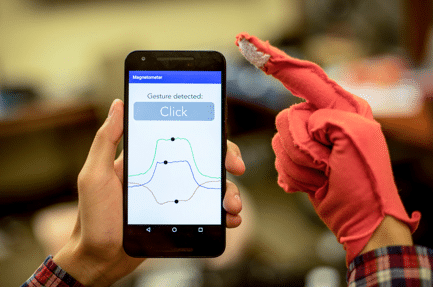 The introduction of conductive threads and wearable electronics together with the introduction of Lilypad Arduino microcontroller and Google’s Project Jacquard has revived the interest in the everyday article of clothing as a computing and interaction platform. How about all that while not the necessity for onboard electronics or batteries? The UW computer researchers have created […]
The post Unlock The Door To Future With Smart Fabric appeared first on Electronics For You.
from Electronics For You https://ift.tt/2JykqjR
Simple Obstacle-Avoiding Robot
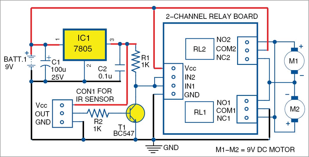 Presented here is an obstacle-avoidance robot without microcontroller (MCU). The obstacle-avoidance feature is commonly found in autonomous cars and robots. Most obstacle-avoidance robots are costly and difficult to build because of MCUs. This project is simple and does not use any complex circuitry except a relay driver. The author’s prototype is shown in Fig. 1. […]
The post Simple Obstacle-Avoiding Robot appeared first on Electronics For You.
from Electronics For You https://ift.tt/2WfNlue
Thursday, 21 March 2019
New Osilloscopes from Keysight Aim For Maker and Education Markets
At APEC 2019, Keysight displayed their InfiniiVision 1000 X-Series with powerful features for most engineers.
from All About Circuits News https://ift.tt/2Okq2wH
from All About Circuits News https://ift.tt/2Okq2wH
TDA 9370 COLOUR TV CHROMA IC DATASHEET AND PINOUT
TDA 9370PS/N3/3/1931 DATA SHEET AND PINOUT
TDA 9370PS/N2/AI1148 DATA SHEET AND PINOUT

TDA9370PS pin voltage tda9370ps/n3/a/1717 pin voltage tda9370ps/n3/a/1930 pin voltage tda9370ps n3 a 1717 pin detail tda9370ps/n3/a/1930 circuit diagram tda9370ps/n3/a/1747 tda9370ps/n3/a/1717 onida tda9370ps/n3/a/1710 datasheet tda9370ps/n3/a/1747 pin details
TDA 9370PS/N2/AI1148 DATA SHEET AND PINOUT

Other ic datas are available in this link
TDA9370PS pin voltage tda9370ps/n3/a/1717 pin voltage tda9370ps/n3/a/1930 pin voltage tda9370ps n3 a 1717 pin detail tda9370ps/n3/a/1930 circuit diagram tda9370ps/n3/a/1747 tda9370ps/n3/a/1717 onida tda9370ps/n3/a/1710 datasheet tda9370ps/n3/a/1747 pin details
TDA9570H/N3/A/1783 COLOUR TV CHROMA IC DATASHEET AND PINOUT
TDA9570H/N3/A/1783


Other ic datas are available in this link
Wednesday, 20 March 2019
Applications And Advantages Of Using Li-Fi For Data Transfer
 Li-Fi, which uses visible light for communication, is 100 times faster than Wi-Fi, which uses radio frequencies. Visible light communication (VLC) is a data communication method that uses visible light between 400THz and 800THz (Tera-Hertz) frequency; wavelength is 780nm to 375nm. It is a subset of optical wireless communication technologies. VLC technology uses fluorescent lamps […]
The post Applications And Advantages Of Using Li-Fi For Data Transfer appeared first on Electronics For You.
from Electronics For You https://ift.tt/2HQIT1p
Silanna Touts Efficiency and Ease of Design with World’s First Active Clamp Flyback Controller
Silanna announces an active clamp flyback controller with built-in UHV components for AC/DC power adapters.
from All About Circuits News https://ift.tt/2JpiV7m
from All About Circuits News https://ift.tt/2JpiV7m
New I/O Expander from Diodes Incorporated Offers Low-Voltage Compatibility
The PI4IOE5V6416 allows you to incorporate 16 additional I/O pins into a wide variety of microcontroller- and FPGA-based applications.
from All About Circuits News https://ift.tt/2ThgHGV
from All About Circuits News https://ift.tt/2ThgHGV
TDA 12155PS N3 3 AT1 COLOUR TV CHROMA IC DATA SHEET
TDA12155PS/N3/3/AT1

1 IFVO
2 VP2
3 VCC AUDIO
4 PLLIF
5GND2
6 DECSDEM
7 FMDEMOUT
8 EHTO
9 AGC
10 IREF
11CSC
12IF IN2
13 IF IN 1
14 VDRA
15 VDRB
16 AVLEW
17 DECBG
18 SECPLL
19 GNG1
20 PHL1FL
21 PHL2FL
22 VP1
23 DECDIG
24 XTALOUT
25 XTALIN
26 IR
27 MUTE
28 TILT
29 KEY
30 BAND2
31 BAND1
32 TUNNING
33 VDDP
34 SCL
35 SDA
36
37 TV/AV
38 STANDBY
39
40 VDD
41GND5
42 VPE
43 VDDA
44 BOUT
45 GOUT
46 ROUT
47 BLKIN
48 BCLIN
49 PB
50 YS/CVBS
51 PR/C3
52 YOUT
53 YSYNC
54 VP3
55 GND 3
56 HOUT
57 FBISO
58 LSR
59 LSL
60 C2/C3/C4
61 AIN3/IN1R
62 CVBSE/Y2
63 A/N2/N1L
64 CVBS4/Y4
Other ic datas are available in this link
tda11105ps/n3/3 datasheet tda11105ps ic pin voltage tda11105ps/v3/3/a04 pin voltage tda11105ps/n3/3/an4 pin voltage tda11105ps/n3/3 pinout tda11105ps/v3/3 ic pin details tda11105ps/v3/3/an4 TDA 12155PS N3 3 AT1 tda12155ps/n3/3/at1 tda12155ps/n3/3/at1 datasheet tda12155ps/n3/3 pdf download tda12155ps/n3/3 equivalent tda12155h/n3/3/ak3 tda 12155 pinout tda12156ps/n3/3 pin details tda 12155 ps n3 3tda11105ps/v3/3/al7
TDA 11105PS / V3/3/AO4 COLOUR TV CHROMA IC DATA SHEET
TDA 11105PS /V3/3/AO4 COLOUR TV CHROMA IC DATA SHEET

TDA 11105PS /N3/3/
1 IFVO
2 VP2
3 VCC AUDIO
4 PLLIF
5GND2
6 DECSDEM
7 FMDEMOUT
8 EHTO
9 AGC
10 IREF
11CSC
12IF IN2
13 IF IN 1
14 VDRA
15 VDRB
16 AVLEW
17 DECBG
18 SECPLL
19 GNG1
20 PHL1FL
21 PHL2FL
22 VP1
23 DECDIG
24 XTALOUT
25 XTALIN
26 IR
27 MUTE
28 TILT
29 KEY
30 BAND2
31 BAND1
32 TUNNING
33 VDDP
34 SCL
35 SDA
36
37 TV/AV
38 STANDBY
39
40 VDD
41GND5
42 VPE
43 VDDA
44 BOUT
45 GOUT
46 ROUT
47 BLKIN
48 BCLIN
49 PB
50 YS/CVBS
51 PR/C3
52 YOUT
53 YSYNC
54 VP3
55 GND 3
56 HOUT
57 FBISO
58 LSR
59 LSL
60 C2/C3/C4
61 AIN3/IN1R
62 CVBSE/Y2
63 A/N2/N1L
64 CVBS4/Y4
Other ic datas are available in this link
tda11105ps/n3/3 datasheet tda11105ps ic pin voltage tda11105ps/v3/3/a04 pin voltage tda11105ps/n3/3/an4 pin voltage tda11105ps/n3/3 pinout tda11105ps/v3/3 ic pin details tda11105ps/v3/3/an4 tda11105ps/v3/3/al7
Tuesday, 19 March 2019
Portable Health Checker Device with Blood Oxygen Monitor Project
Download Project Document/Synopsis With rapid medical development of our modern societies, the health care systems are becoming much more mature and professional. In order to reduce the current burden of public health system and promote the popularity of routine health self-check, this technique has been developed for making faster and accurate pre diagnoses with ease-of-use. […]
The post Portable Health Checker Device with Blood Oxygen Monitor Project appeared first on NevonProjects.
from NevonProjects https://ift.tt/2OfxFEt
Advanced Car & Scooty Training Driving School Management System
Download Project Document/Synopsis This Advanced Motor Driving School Management system can reduce the efforts of human power and wealth very much, and ensure driving-training school’s information resource to be utilized effectively. The motor driving trainers has to handle several students at a time. This will provide drawback in terms of communicating with students for his […]
The post Advanced Car & Scooty Training Driving School Management System appeared first on NevonProjects.
from NevonProjects https://ift.tt/2Oh1IMo
Monday, 18 March 2019
Advanced Employee Management System Project Using PHP
Download Project Document/Synopsis Human resources describe the people who work for a company or organization and the department is responsible for managing resources related to employees. A human resource is a single person or employee within your organization. Human resources refer to all of the people you employ. The manual method is used to maintain […]
The post Advanced Employee Management System Project Using PHP appeared first on NevonProjects.
from NevonProjects https://ift.tt/2W9oJTT
Mobility: Electronic Toll, Standing Tall
 Electronic toll collection technology was developed to eliminate delays on toll roads by collecting tolls electronically. Recently, frequent traffic jams at Sirhaul Toll Plaza on Delhi-Gurugram expressway forced the district administration to close the 12-lane plaza permanently. People commuting from New Delhi to Gurugram and back recall the difficulty faced in passing through this toll […]
The post Mobility: Electronic Toll, Standing Tall appeared first on Electronics For You.
from Electronics For You https://ift.tt/2TIV7jH
Understanding DNL and INL Specifications of a DAC
This article will examine some properties of the DNL and INL specifications.
from All About Circuits Technical Articles https://ift.tt/2TPPq3D
from All About Circuits Technical Articles https://ift.tt/2TPPq3D
APEC 2019 Focuses on the Needs of the Practical, Practicing Power Engineer
Learn what's in store and get the latest power engineering news from AAC reporting live from the conference.
from All About Circuits News https://ift.tt/2Tfxr1g
from All About Circuits News https://ift.tt/2Tfxr1g
How To Use Modern Multi-Processor Application Programs
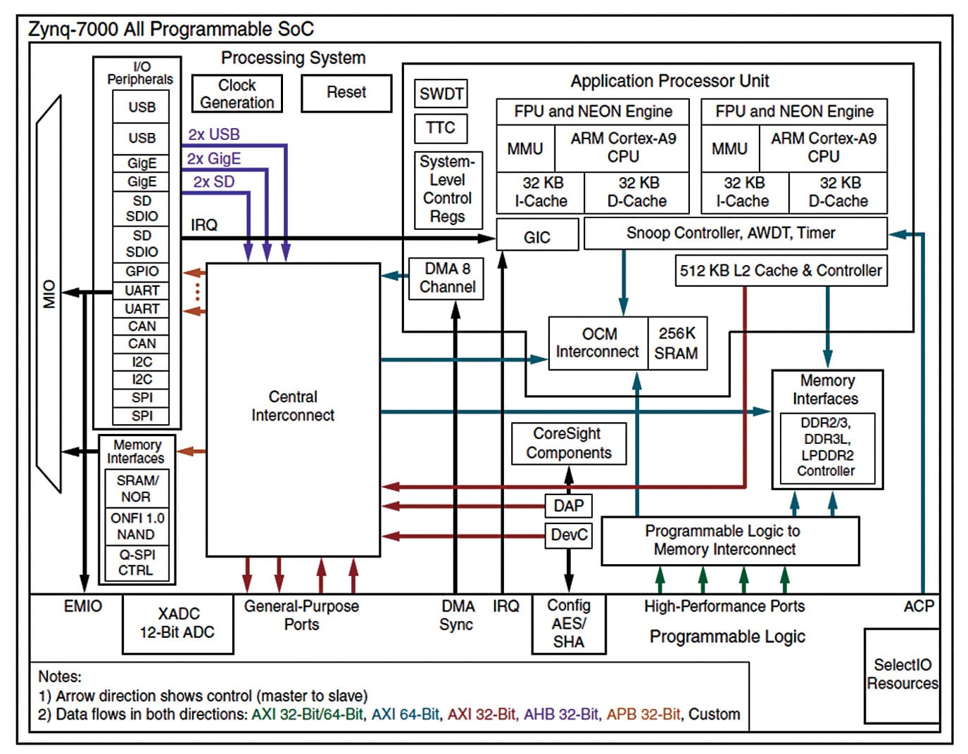 An application built with the hybrid model of parallel programming can run on a computer cluster using both OpenMP and message passing interface. Modern embedded applications are becoming complex and demanding with respect to code reuse, as platforms and applications are being developed and implemented rapidly. Implementation is a combination of hardware and software, and […]
The post How To Use Modern Multi-Processor Application Programs appeared first on Electronics For You.
from Electronics For You https://ift.tt/2HsMR0O
Saturday, 16 March 2019
Can Near Field Communication Be Secure In the IoT? NXP’s New NFC Tag Aims For Highest Security
Despite security fears, RFID and NFC use is growing. NXP aims to make NFC more secure with its NTAG 424 DNA.
from All About Circuits News https://ift.tt/2TEOZcg
from All About Circuits News https://ift.tt/2TEOZcg
Cobots And Augmented Reality Changing The World
 In this article, we discuss cobots and AR from the perspective of motivation, technology and business, while adding a social spin to these. Cobots (or collaborative robots) and augmented reality (AR) are advancing societal development. Cobots are finding use in sectors like manufacturing and medical for detecting errors and increasing productivity and, hence, motivating entrepreneurs […]
The post Cobots And Augmented Reality Changing The World appeared first on Electronics For You.
from Electronics For You https://ift.tt/2u7jKHA
Friday, 15 March 2019
Ensuring Safety While Filling Air Inside A Tyre
 In this article, our focus is related to air pressure while filling air in the tyre. This is important because the tyre may get burst and create many other problems due to excessive air pressure inside. So, we have proposed one method in which, one can detect the pressure of air in the tyre while […]
The post Ensuring Safety While Filling Air Inside A Tyre appeared first on Electronics For You.
from Electronics For You https://ift.tt/2UFX5hc
Subscribe to:
Posts (Atom)