Klystron amplifiers are used in a variety of industries, including satellite systems, television broadcasting, radar, particle accelerators, and in the medical field. In this article, we'll learn about the two-cavity klystron's unique build and the concept of electron bunching.
from All About Circuits Technical Articles https://ift.tt/2vo0yWi
Tuesday, 31 July 2018
The Quantum Race: Roundup on Quantum Cryptosecurity, Programming Languages, and Development
The space race of the cold war saw the US and Russia develop a wide range of aerospace technologies. But a new race is about to begin, mostly among corporations, and the winner will unlock the power of the quantum computing realm.
from All About Circuits News https://ift.tt/2Oynwmr
from All About Circuits News https://ift.tt/2Oynwmr
How To Build an Arduino Wireless Network with Multiple NRF24L01 Modules
In this tutorial we will learn how to build an Arduino wireless network, composed of multiple NR24L01 transceiver modules. You can watch the following video or read the written tutorial below.
Overview
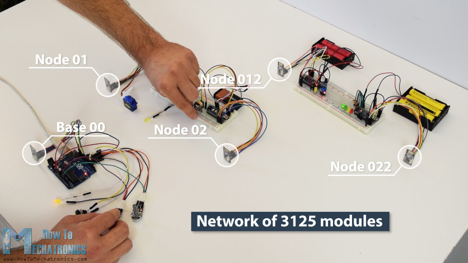
As an example I made a network of 5 nodes and each of them can communicate with any node in the network and at the same time they can work as both transmitters and receivers. This example is actually set up in a way that explains how to make a much larger network, or to be precise, we can have a total of 3125 modules communicating to each other on a single RF channel. So let’s take a look how it works.
In my previous tutorials we have already learned how to make a wireless communication between two Arduino boards using the NRF24L01 modules and the RF24 library. Now in addition to this library, we will use the RF24Network library, which enables in an easy way to build a wireless network with many Arduino boards communicating to each other. Here’s how the network topology works.
A single NRF24L01 module can actively listen up to 6 other modules at the same time.
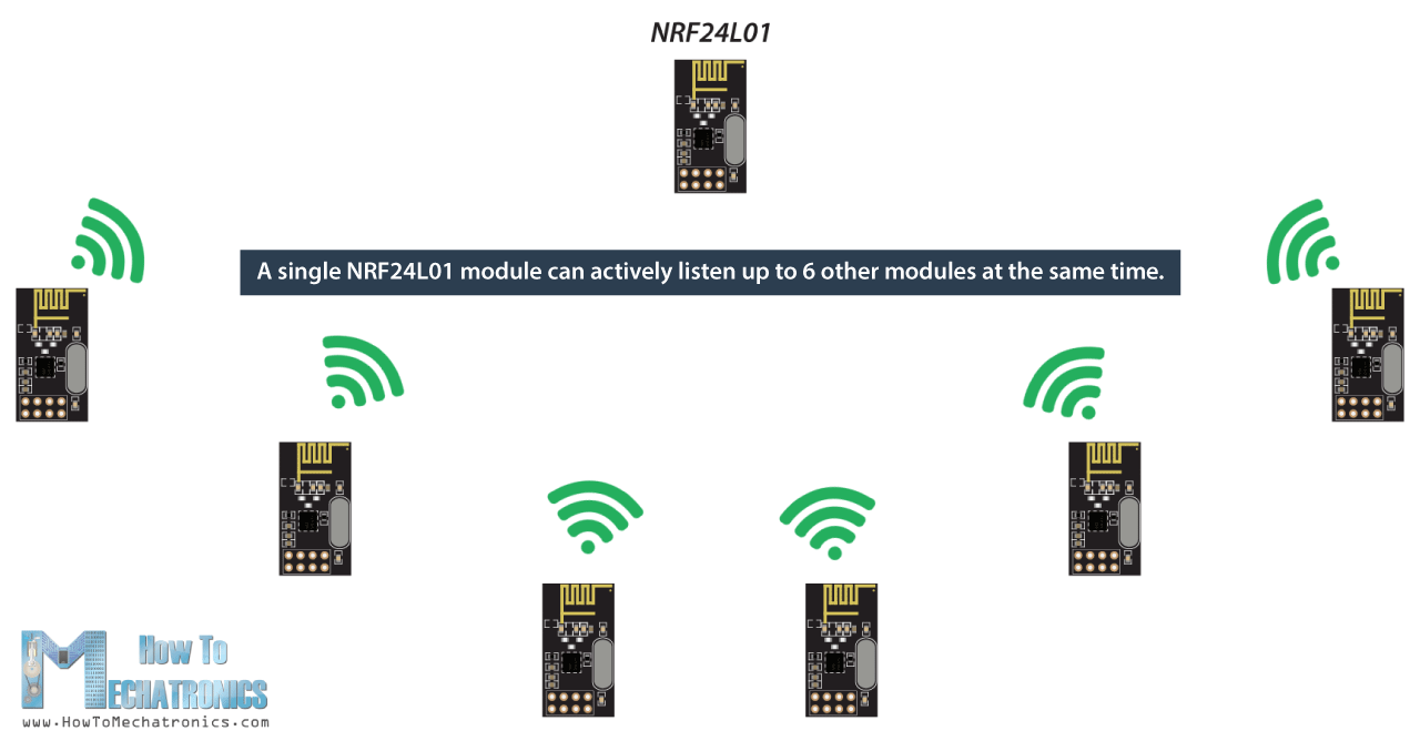
This ability is utilized by the RF24Network library to generate a network arranged in a tree topology, where one node is the base, and all other nodes are children of either that node or of another. Each node can have up to 5 children, and this can go 5 levels deep, which means we can create a network of total 3125 nodes. Each node must be defined with a 15-bit address, which precisely describes the position of the node within the tree.
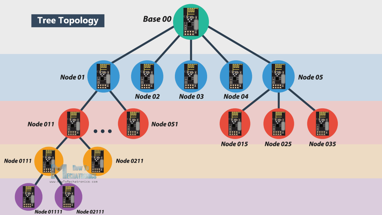
We can actually define the addresses of the nodes in octal format. So, the address of the master or the base is 00, the base children addresses are 01 to 05, the 01 node children addresses are 011 to 051 and so on.
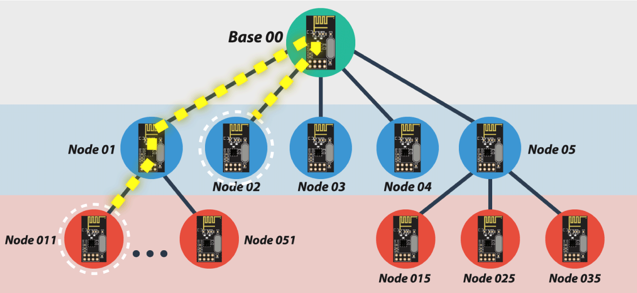
Note that if node 011 wants to talk to the node 02, the communication will have to go through the node 01 and the base node 00, so these two nodes must be active all the time in order the communication to be successful.
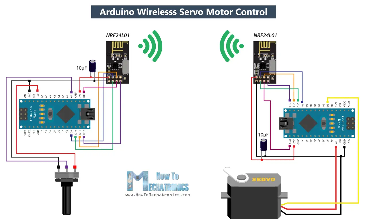
Arduino Wireless Servo Motor Control using the RF24Network Library
Before we explain the main example of this tutorial, for better understanding how the library works let’s make a simpler example of two Arduinos communicating to each other. Here’s the circuit diagram for this example.
You can get the components needed for this Arduino Tutorial from the links below:
- NRF24L01 Transceiver Module…………. Amazon / Aliexpress
- Arduino Board ………………………………… Amazon / Aliexpress
*Please note: These are affiliate links. I may make a commission if you buy the components through these links.
I would appreciate your support in this way!
So using the potentiometer at the first Arduino we will control the servo motor at the second Arduino. Let’s take a look at the source codes now.
Here’s the code at the potentiometer side:
/*
  Arduino Wireless Network - Multiple NRF24L01 Tutorial
 == Example 01 - Servo Control / Node 00 - Potentiometer ==
  by Dejan, www.HowToMechatronics.com
  Libraries:
  nRF24/RF24, https://github.com/nRF24/RF24
  nRF24/RF24Network, https://github.com/nRF24/RF24Network
*/
#include <RF24.h>
#include <RF24Network.h>
#include <SPI.h>

RF24 radio(10, 9);               // nRF24L01 (CE,CSN)
RF24Network network(radio);      // Include the radio in the network
const uint16_t this_node = 00;   // Address of this node in Octal format ( 04,031, etc)
const uint16_t node01 = 01;

void setup() {
  SPI.begin();
  radio.begin();
  network.begin(90, this_node);  //(channel, node address)
}

void loop() {
  network.update();
  unsigned long potValue = analogRead(A0);  // Read the potentiometer value
  unsigned long angleValue = map(potValue, 0, 1023, 0, 180); // Convert the value to 0-180
  RF24NetworkHeader header(node01);     // (Address where the data is going)
  bool ok = network.write(header, &angleValue, sizeof(angleValue)); // Send the data
}
First we need to include both libraries RF24 and RF24Network, as well as the SPI library. Then we need to create the RF24 object, and include it into the RF24Network object. Here we need define the addresses of the nodes in octal format, or 00 for this node, and 01 for the other node at the servo side.
In the setup section we need to initialize the network, by setting the channel and the address of this node.
In the loop section we constantly need to call the update() function through which all action in the network happens. Then we read the value of the potentiometer and convert it into a value from 0 to 180 which is suitable for the servo control. Then we create a network header where we assign the address of the node where the data is going. At the end, using the write() function we send the data to the other node. So here the first parameter contains the addresses information, the second parameter points which data will be send, and the third parameter is the size of the data.
Here’s the code at the servo side:
/*
  Arduino Wireless Network - Multiple NRF24L01 Tutorial
  == Example 01 - Servo Control / Node 01 - Servo motor ==
*/
#include <RF24.h>
#include <RF24Network.h>
#include <SPI.h>
#include <Servo.h>

RF24 radio(10, 9);               // nRF24L01 (CE,CSN)
RF24Network network(radio);      // Include the radio in the network
const uint16_t this_node = 01;   // Address of our node in Octal format ( 04,031, etc)

Servo myservo;  // create servo object to control a servo

void setup() {
  SPI.begin();
  radio.begin();
  network.begin(90, this_node); //(channel, node address)
  myservo.attach(3);   // (servo pin)
}

void loop() {
  network.update();
  while ( network.available() ) {     // Is there any incoming data?
    RF24NetworkHeader header;
    unsigned long incomingData;
    network.read(header, &incomingData, sizeof(incomingData)); // Read the incoming data
    myservo.write(incomingData);  // tell servo to go to a particular angle
  }
}
On the other side, at the servo motor, we need to define the libraries and the objects in the same way as explained earlier. Here the address of this node in octal format is 01. After defining the servo motor, in the loop section, using the while() loop and the available() function we constantly check whether there is any incoming data. If true, we create a network header through which the data will be accepted and also a variable where the data will be stored. Then using the read() function we read the data, and store it into the incomingData variable. At the end we use this data to move the servo motor according to the potentiometer from the other node.
Arduino Wireless Network with Multiple NRF24L01 Modules
After understanding this example we can move on with the main example of this tutorial and build a wireless network of 5 Arduinos communicating to each other. Here’s a block diagram of the example.
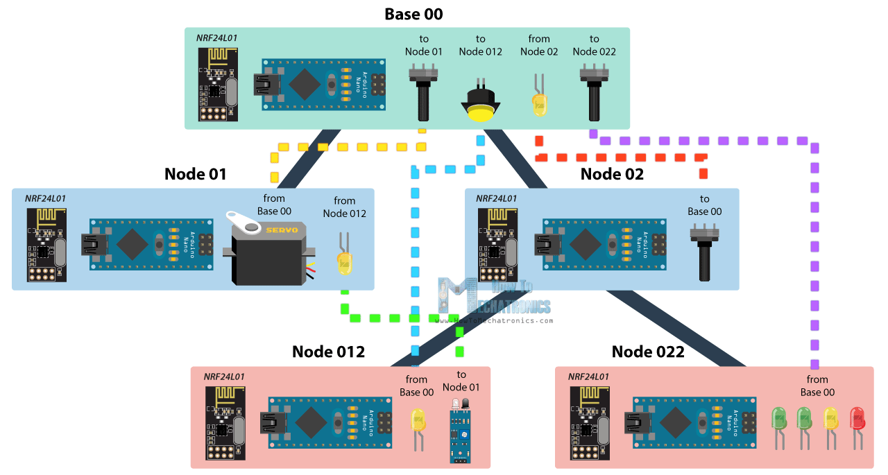
So from the base, using a potentiometer we will control the servo motor at the node 01, with the second potentiometer we will control the LEDs at the node 022, using the button we will control the LED at node 012, and the LED here at the base will be control using the potentiometer at node 02. Also using the infrared sensor at the node 012 we will control the LED at node 01. So we can notice that this example explains how to both transmit and receive data at the same time, as well as how to communicate with nodes from different branches. Let’s take a look at the Arduino codes now.
Base 00 source code
/*
  Arduino Wireless Network - Multiple NRF24L01 Tutorial
          == Base/ Master Node 00==
  by Dejan, www.HowToMechatronics.com
  Libraries:
  nRF24/RF24, https://github.com/nRF24/RF24
  nRF24/RF24Network, https://github.com/nRF24/RF24Network
*/

#include <RF24Network.h>
#include <RF24.h>
#include <SPI.h>

#define button 2
#define led 3

RF24 radio(10, 9);               // nRF24L01 (CE,CSN)
RF24Network network(radio);      // Include the radio in the network
const uint16_t this_node = 00;   // Address of this node in Octal format ( 04,031, etc)
const uint16_t node01 = 01;      // Address of the other node in Octal format
const uint16_t node012 = 012;
const uint16_t node022 = 022;

void setup() {
  SPI.begin();
  radio.begin();
  network.begin(90, this_node);  //(channel, node address)
  radio.setDataRate(RF24_2MBPS);
  pinMode(button, INPUT_PULLUP);
  pinMode(led, OUTPUT);
}

void loop() {
  network.update();
  //===== Receiving =====//
  while ( network.available() ) {     // Is there any incoming data?
    RF24NetworkHeader header;
    unsigned long incomingData;
    network.read(header, &incomingData, sizeof(incomingData)); // Read the incoming data
    analogWrite(led, incomingData);    // PWM output to LED 01 (dimming)
  }
  //===== Sending =====//
  // Servo control at Node 01
  unsigned long potValue = analogRead(A0);
  unsigned long angleValue = map(potValue, 0, 1023, 0, 180); // Suitable for servo control
  RF24NetworkHeader header2(node01);     // (Address where the data is going)
  bool ok = network.write(header2, &angleValue, sizeof(angleValue)); // Send the data

  // LED Control at Node 012
  unsigned long buttonState = digitalRead(button);
  RF24NetworkHeader header4(node012);    // (Address where the data is going)
  bool ok3 = network.write(header4, &buttonState, sizeof(buttonState)); // Send the data

  // LEDs control at Node 022
  unsigned long pot2Value = analogRead(A1);
  RF24NetworkHeader header3(node022);    // (Address where the data is going)
  bool ok2 = network.write(header3, &pot2Value, sizeof(pot2Value)); // Send the data
}
So at the base or the master node we need to define the libraries and the objects as explained earlier, and also define all other nodes to which the master will send data. In the loop section we start by constantly checking whether there is any incoming data. If so, we read the data, store it into the incomingData variable and use it to control the LED brightness. This data is actually coming from the potentiometer from node 02. If we take a look at its code, we can notice that setup is pretty much the same. The important thing is to assign the right address to where we want to send data. In this case, that’s the master 00. So after reading the potentiometer value and converting it into suitable PWM value from 0 to 255, we send this data to the master. We can notice here that I used the millis() function send the data at intervals of 10 milliseconds.
Node 02 source code
/*
  Arduino Wireless Network - Multiple NRF24L01 Tutorial
        == Node 02 (Child of Master node 00) ==
*/

#include <RF24Network.h>
#include <RF24.h>
#include <SPI.h>

RF24 radio(10, 9);               // nRF24L01 (CE,CSN)
RF24Network network(radio);      // Include the radio in the network
const uint16_t this_node = 02;   // Address of our node in Octal format ( 04,031, etc)
const uint16_t master00 = 00;    // Address of the other node in Octal format

const unsigned long interval = 10;  //ms  // How often to send data to the other unit
unsigned long last_sent;            // When did we last send?

void setup() {
  SPI.begin();
  radio.begin();
  network.begin(90, this_node);  //(channel, node address)
  radio.setDataRate(RF24_2MBPS);
}

void loop() {
  network.update();
  //===== Sending =====//
  unsigned long now = millis();
  if (now - last_sent >= interval) {   // If it's time to send a data, send it!
    last_sent = now;
    unsigned long potValue = analogRead(A0);
    unsigned long ledBrightness = map(potValue, 0, 1023, 0, 255);
    RF24NetworkHeader header(master00);   // (Address where the data is going)
    bool ok = network.write(header, &ledBrightness, sizeof(ledBrightness)); // Send the data
  }
}
Next, from the master, we send the potentiometer data to the node 01 for controlling the servo motor.
Node 01 source code
/*
  Arduino Wireless Network - Multiple NRF24L01 Tutorial
        == Node 02 (Child of Master node 00) ==
*/

#include <RF24Network.h>
#include <RF24.h>
#include <SPI.h>
#include <Servo.h>

#define led 2

RF24 radio(10, 9);               // nRF24L01 (CE,CSN)
RF24Network network(radio);      // Include the radio in the network
const uint16_t this_node = 01;   // Address of our node in Octal format ( 04,031, etc)
const uint16_t master00 = 00;    // Address of the other node in Octal format

Servo myservo;  // create servo object to control a servo

void setup() {
  SPI.begin();
  radio.begin();
  network.begin(90, this_node); //(channel, node address)
  radio.setDataRate(RF24_2MBPS);
  myservo.attach(3);   // (servo pin)
  pinMode(led, OUTPUT);
}

void loop() {
  network.update();
  //===== Receiving =====//
  while ( network.available() ) {     // Is there any incoming data?
    RF24NetworkHeader header;
    unsigned long incomingData;
    network.read(header, &incomingData, sizeof(incomingData)); // Read the incoming data
    if (header.from_node == 0) {    // If data comes from Node 02
      myservo.write(incomingData);  // tell servo to go to a particular angle
    }
    if (header.from_node == 10) {    // If data comes from Node 012
      digitalWrite(led, !incomingData);  // Turn on or off the LED 02
    }
  }
}
The node 01 is actually receiving data from two different nodes, one for the servo control and the other for the LED control which comes from the infrared sensor from the node 012.
Node 012 source code
/*
  Arduino Wireless Network - Multiple NRF24L01 Tutorial
            == Node 012 (child of Node 02)==
*/

#include <RF24Network.h>
#include <RF24.h>
#include <SPI.h>

#define led 2
#define IR 3

RF24 radio(10, 9);               // nRF24L01 (CE,CSN)
RF24Network network(radio);      // Include the radio in the network
const uint16_t this_node = 012;  // Address of our node in Octal format ( 04,031, etc)
const uint16_t node01 = 01;    // Address of the other node in Octal format

void setup() {
  SPI.begin();
  radio.begin();
  network.begin(90, this_node);  //(channel, node address)
  radio.setDataRate(RF24_2MBPS);
  pinMode(led, OUTPUT);
  pinMode(IR, INPUT);
}

void loop() {
  network.update();
  //===== Receiving =====//
  while ( network.available() ) {     // Is there any incoming data?
    RF24NetworkHeader header;
    unsigned long buttonState;
    network.read(header, &buttonState, sizeof(buttonState)); // Read the incoming data
    digitalWrite(led, !buttonState); // Turn on or off the LED
  }
  //===== Sending =====//
  unsigned long irV = digitalRead(IR); // Read IR sensor
  RF24NetworkHeader header8(node01);
  bool ok = network.write(header8, &irV, sizeof(irV)); // Send the data
}
In such a case, we use the header.from_node attribute in order get information from which node does the data come from. In case the incoming data is from the master, we use it to control the servo, and in case the incoming data is from the node 012, we use it to control the LED.
At the node 012 we have both transmitting and receiving. The infrared sensor controls the previously mentioned LED at node 01 and the LED here is control from the button at the master.
Node 022 source code
/*
  Arduino Wireless Network - Multiple NRF24L01 Tutorial
            == Node 022 (child of Node 02)==
*/

#include <RF24Network.h>
#include <RF24.h>
#include <SPI.h>

#define led1 2
#define led2 3
#define led3 4
#define led4 5

RF24 radio(10, 9);               // nRF24L01 (CE,CSN)
RF24Network network(radio);      // Include the radio in the network
const uint16_t this_node = 022;  // Address of our node in Octal format ( 04,031, etc)
const uint16_t master00 = 00;    // Address of the other node in Octal format

void setup() {
  SPI.begin();
  radio.begin();
  network.begin(90, this_node);  //(channel, node address)
  radio.setDataRate(RF24_2MBPS);
  pinMode(led1, OUTPUT);
  pinMode(led2, OUTPUT);
  pinMode(led3, OUTPUT);
  pinMode(led4, OUTPUT);
}

void loop() {
  network.update();
  //===== Receiving =====//
  while ( network.available() ) {     // Is there any incoming data?
    RF24NetworkHeader header;
    unsigned long potValue;
    network.read(header, &potValue, sizeof(potValue)); // Read the incoming data
    // Turn on the LEDs as depending on the incoming value from the potentiometer
    if (potValue > 240) {
      digitalWrite(led1, HIGH);
    } else {
      digitalWrite(led1, LOW);
    }
    if (potValue > 480) {
      digitalWrite(led2, HIGH);
    } else {
      digitalWrite(led2, LOW);
    }
    if (potValue > 720) {
      digitalWrite(led3, HIGH);
    } else {
      digitalWrite(led3, LOW);
    }
    if (potValue > 960) {
      digitalWrite(led4, HIGH);
    } else {
      digitalWrite(led4, LOW);
    }
  }
}
Finally, the LEDs at node 022 are controlled using the data coming from the other potentiometer at the master.
So, to sum up, if everything is connected properly, and all of the nodes are active all the time, our job boils down to just precisely addressing the nodes and all the heavy work behind is carried out by the incredible RF24Network library.
So that would be all, I hope you enjoyed this Arduino project and learned something new. Feel free to ask any question in the comments section below.
The post How To Build an Arduino Wireless Network with Multiple NRF24L01 Modules appeared first on HowToMechatronics.
from HowToMechatronics https://ift.tt/2M2G5x9
The Quantum Race: Roundup on Quantum Cryptosecurity, Programming Languages, and Development
The space race of the cold war saw the US and Russia develop a wide range of aerospace technologies. But a new race is about to begin, mostly among corporations, and the winner will unlock the power of the quantum computing realm.
from All About Circuits News https://ift.tt/2Oynwmr
from All About Circuits News https://ift.tt/2Oynwmr
Basics of RF Bias Tees
 Bias Tees are RF components that are used whenever you need to couple a DC, power or low-speed control signal onto an RF signal path. This video discusses the basics of Bias Tees, how they work, examples of practical construction and a few lab application examples. Courtesy: w2aew
The post Basics of RF Bias Tees appeared first on Electronics For You.
from Electronics For You https://ift.tt/2LKS8T5
Understanding 5G In Perspective of Industry Specific Trends
 Like 2G, 3G and 4G, 5G is not a distinctive sliver, it is a landscape altogether. 5G is essentially about a vision that techno savvy people have in combination, for the uses of currently evolved technologies for the better applicability on most modernize applications. In that sense it is not another cellular system only, or […]
The post Understanding 5G In Perspective of Industry Specific Trends appeared first on Electronics For You.
from Electronics For You https://ift.tt/2M5I048
TP4056 Lithium Ion Battery Charger
In this project, we will learn about TP4056 Lithium Ion Battery Charger which is based on the TP4056 Li-Ion Battery Charger IC. In the process, I will discuss the circuit diagram of the TP4056 Lithium Ion Battery Charger module, components on the module and how to connect an 18650 battery to this module and charge it.
WARNING: Working with batteries is extremely dangerous and if you are not familiar with the connections, results might be fatal. Battery might explode if wrongly used.
Introduction
Almost all the electronic devices and gadgets run on battery power now-a-days. You can find many devices like Mobile Phones, Tablets, Laptops, Cameras, etc. that run on battery.
Apart from the small devices mentioned above, Cars, Motorcycles, electric vehicles also contain battery and require a battery charger mechanism.
And when a battery is involved, a Battery Charger is also involved. Battery Chargers are devices that recharge the batteries by putting energy into them.
In this project, I will talk about one such battery charger module for charging Lithium Ion Batteries. It is TP4056 Li-Ion Battery Charger.
Also read: HOW TO MAKE AN AUTOMATIC BATTERY CHARGER?
A Brief Note on TP4056 Lithium Battery Charge Controller
The TP4056 is a low-cost Lithium Ion battery charger controller IC. It supports a constant current – constant voltage charging mechanism for s single cell Li-Ion Battery.
It is available in 8-pin SOP package and requires very minimum external components in order to build a Lithium Ion battery charger circuit.
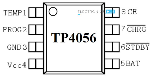
Pin Diagram of TP4056 Lithium Ion Battery Charger IC
The following image shows the pin diagram of the TP4056 Li-Ion Battery Charger IC. It is an 8-pin IC and the pins are TEMP, PROG, GND, VCC, BAT, , and CE.
|
Pin Number |
Pin Name |
Function |
|
1 |
TEMP |
Temperature Sense |
|
2 |
PROG |
Constant Charge Current Setting |
|
3 |
GND |
Ground |
|
4 |
VCC |
Supply |
|
5 |
BAT |
Battery Connection Pin |
|
6 |
STDBY |
Standby Pin |
|
7 |
CHRG |
Charging Pin |
|
8 |
CE |
Chip Enable |
Pin Description
Now, let us see the description and function of each pin of TP4056 IC.
- TEMP: It is an input pin for sensing the temperature. It is connected to the output of the NTC Thermistor in a Battery Pack. Based on the voltage at this pin, you can determine the temperature of the Battery. Battery Temperature is too low if voltage is less than 45% of VCC for more than 0.15S or it is too high if voltage is more than 80% of VCC for the same duration.
- PROG: The charge current to the battery is set by connecting a Resistor called RPROG between this pin and GND. Based on the value of the resistor, the charge current can be anywhere from 130mA to 1000A.
- GND: Ground Pin.
- VCC: It is the power supply pin. TP4056 can support a maximum of 8V at VCC but typically 5V is used.
- BAT: It is the battery connection pin connected to the positive terminal of the battery. The voltage at this pin is 4.2V.
- STDBY: When the battery is completely charged, this pin is pulled low. An LED is connected to this to indicate standby mode.
- CHRG: When the battery is charging, this pin is pulled low. An LED is connected to this pin to indicate battery charging.
- CE: It is an input pin for enabling the chip into operation or disabling it. When a HIGH input is given, the TP4056 is in normal mode and when a HIGH input is given, the IC is disabled.
Controlling the Charge Current
As mentioned earlier, the PROG (Pin 2) is used to control the charge current to the battery. It is controlled with the help of a resistor called RPROG. The following table shows a list of charging current values for the corresponding RPROG values.
|
RPROG in KΩ |
IBAT in mA |
|
10 |
130 |
|
5 |
250 |
| 4 |
300 |
|
3 |
400 |
|
2 |
580 |
|
1.66 |
690 |
|
1.5 |
780 |
|
1.33 |
900 |
|
1.2 |
1000 |
This is calculated using the formula IBAT = (VPROG / RPROG) * 1200 and VPROG = 1V.
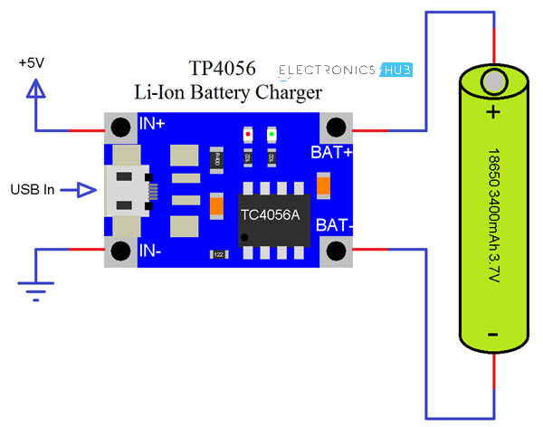
Circuit Diagram of TP4056 Lithium Ion Battery Charger
As mentioned earlier, very few external components are required for building a complete Li-Ion Battery Charger circuit using the TP4056 IC. The following image shows the circuit diagram of one such implementation.
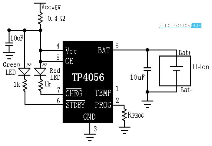
The components needed are as follows:
- TP4056 IC
- LEDs x 2
- 1KΩ Resistor x 2
- 0.4Ω Resistor
- 10µF Capacitor x 2
- 1.2KΩ Resistor (RPROG)
TP4056 Li-Ion Battery Charger Module
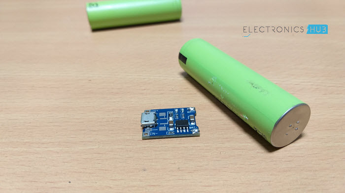
Based on the TP4056 Lithium Ion Battery Charger Controller IC and the above shown circuit diagram, several Li-Ion Battery Charger Modules are developed. The following image shows the module used in this project.
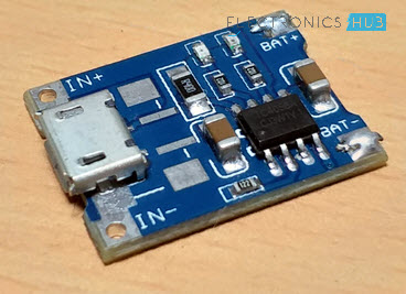
It is a tiny module with all the components mentioned in the above circuit diagram. If you notice, there is a Micro USB connector at the input side of the board. Using this, you can charge a Li-Ion battery from an USB source.
Otherwise, there are connectors for Input Voltage as well as terminals for connecting the Battery. The RPROG resistor on this module is of 1.2KΩ. Hence, this module supports a 1A (1000mA) charging current.
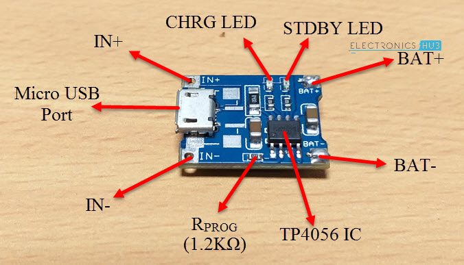
Rest of the components and parts are mentioned in the image above.
NOTE: This module and the circuit shown above doesn’t include the temperature measurement.
Charging an 18650 Lithium Ion Battery with TP4056
18650 Li-Ion batteries are very commonly found Lithium Ion batteries. They are used in Laptops, power banks, etc. I have dismantled an unused laptop battery and extracted three 18650 Batteries.
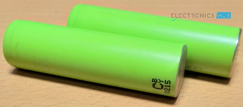
WARNING: Dismantling laptop batteries can be hazardous. We do not recommend it.
If you have 18650 Li-Ion batteries, connect one battery as shown in the following connection diagram. You can charge only one battery at a time. In order to charge the battery, you can either use the IN+ and IN- terminals and provide 5V or alternatively, you can use an USB cable to directly charge from USB supply.
Applications
TP4056 Lithium Ion Battery Charger Module (or the IC) can be used in many applications like:
- Mobile Phones
- GPS Devices
- Digital Cameras
- Power Banks
- USB Chargers
- Handheld Computers
The post TP4056 Lithium Ion Battery Charger appeared first on Electronics Hub.
from Electronics Hub https://ift.tt/2vi7nbC
Monday, 30 July 2018
Considerations for Adding Reset Capability to an FPGA Design
This article will look at some of the consequences of adding a reset input to an FPGA design.
from All About Circuits Technical Articles https://ift.tt/2LUkjyK
from All About Circuits Technical Articles https://ift.tt/2LUkjyK
Power Storage for Renewables: The History of Batteries and the Advent of the Virtual Power Station
With renewable energies on the rise there is a growing need for high capacity energy storage and one possible solution are “virtual power plants”. What is a virtual power plant?
from All About Circuits News https://ift.tt/2vgK6ag
from All About Circuits News https://ift.tt/2vgK6ag
15 Awesome Automation Projects
 Automation allows the benefit of automating tasks and minimizing human involvement. This has led to a lot of people working on automation projects, as these are fun to create and have around the house. Here we look at some automation projects that you can use around your house to reduce effort. Many of these automation […]
The post 15 Awesome Automation Projects appeared first on Electronics For You.
from Electronics For You https://ift.tt/2NROowi
Light Animations Using Arduino and MATLAB
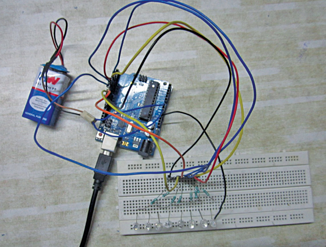 Light animations are visually appealing and hence widely used for advertising purposes. In this project, we present a MATLAB-based graphical user interface (GUI) approach to control the glowing pattern of a number of light-emitting diodes (LEDs). Use of GUI is advantageous since the user can control illumination patterns while performing other tasks in the PC. […]
The post Light Animations Using Arduino and MATLAB appeared first on Electronics For You.
from Electronics For You https://ift.tt/2OqADG2
Saturday, 28 July 2018
Google Plans Big for Indian Public Wifi Market
 Wi-Fi services beyond railway stations to public places such as malls, cafés and universities For the expansion, Google is in talks with several stakeholders including telecom operators, internet service providers (ISPs) and state governments. The US-based tech firm has completed the rollout of RailWire Wi-Fi across 400 railway stations in partnership with RailTel in India. […]
The post Google Plans Big for Indian Public Wifi Market appeared first on Electronics For You.
from Electronics For You https://ift.tt/2LHwe2Z
Mobile Game may Combat Gender-Bias
 Channelising technology to empower women and to question gender-based discrimination In order to combat gender discriminatory practices, Vodafone Foundation and Girl Rising have collaborated to develop the Girl Rising Game. The collaboration is a step towards utilising technology solutions to create a social impact. Enabling education for women Questioning age-old beliefs and the normalisation of […]
The post Mobile Game may Combat Gender-Bias appeared first on Electronics For You.
from Electronics For You https://ift.tt/2OnDU99
Symica: Circuit Design and Simulation Tools for All
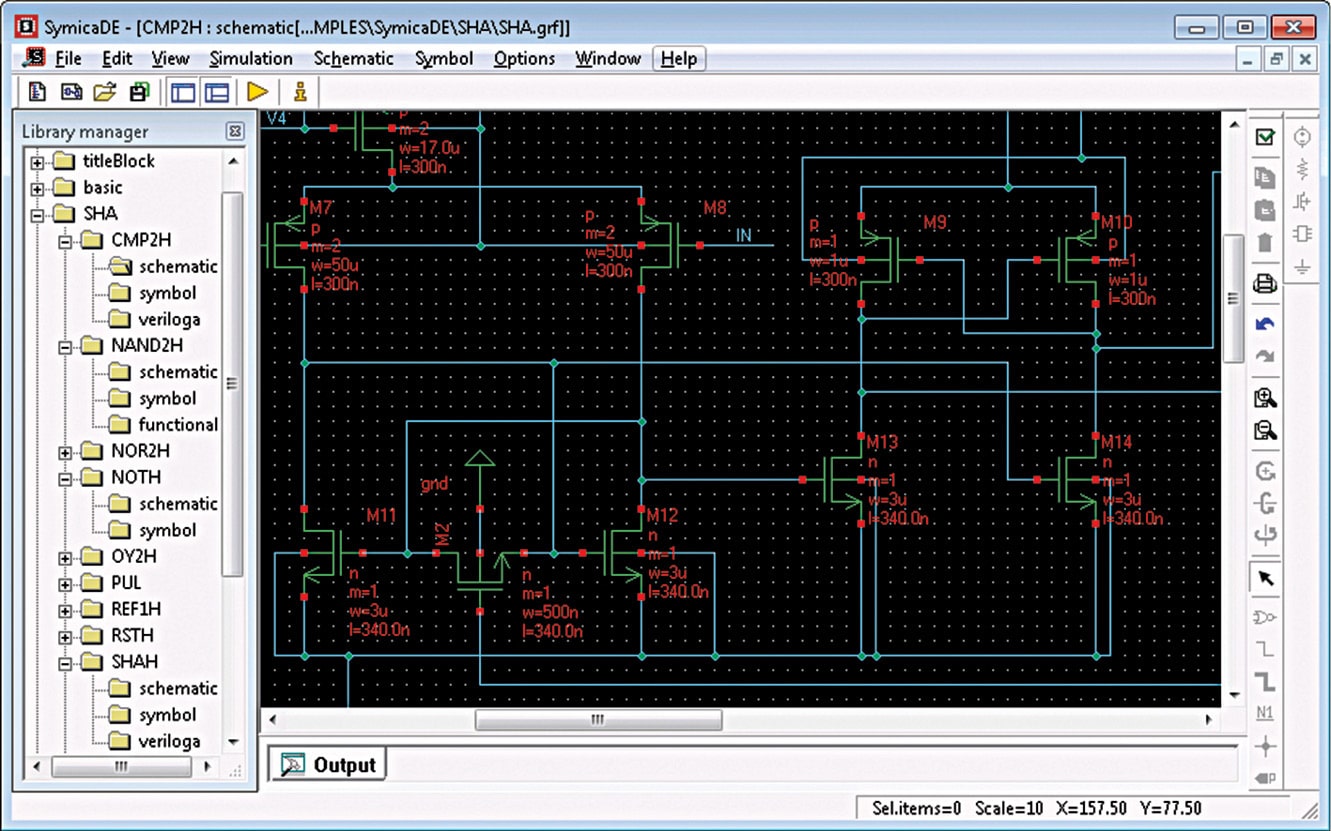 Symica software suite makes IC design easy and accurate. By including various tools including schematic editor, simulator (using SPICE), waveform viewer and analyser, it provides a complete ecosystem to design and develop electronic systems. Symica is compatible with Windows and Linux. It comes both as a free edition (FE) and paid version. Unlike full (paid) […]
The post Symica: Circuit Design and Simulation Tools for All appeared first on Electronics For You.
from Electronics For You https://ift.tt/2vagdZ7
Digital Transformation Can Boost the Growth of Indian Storage Industry
 With the rise of connected devices, the amount of data generated is growing manifold. While technologies like Big Data, machine learning and artificial intelligence (AI) help derive meaningful insights, its management remains a challenge. To understand how data from various sources can be managed better, Ankita KS from EFY had an interaction with senior vice […]
The post Digital Transformation Can Boost the Growth of Indian Storage Industry appeared first on Electronics For You.
from Electronics For You https://ift.tt/2mOENec
How to use Hall Effect Sensor with Arduino?
In this project, we will learn about Hall Effect Sensor, how a Hall Effect IC works, block diagram of a typical Hall Effect IC and how to interface a Hall Effect Sensor with Arduino. Additionally, I will show you how to control a Relay using Hall Effect Sensor and Arduino.
Introduction
If you remember the Arduino WaterFlow Sensor Tutorial we implemented earlier, the main component of the Water Flow Sensor is the Hall Effect IC.
A Hall Effect Sensor works on the principle of, well, Hall Effect. Simply speaking, a Hall Effect Sensor or IC detects motion, position or change in magnetic field strength of either a permanent magnet, an electromagnet or any ferromagnetic material.
Hall Effect IC are contact-less magnetically activated switches. They are used in a wide range of applications like automobiles, computers, control systems, security systems etc.
So, in this project, I will discuss about a Hall Effect IC A11004, how this Hall Effect Sensor works and finally how to interface a Hall Effect Sensor with Arduino.
A Brief Note on Hall Effect Sensor
As mentioned earlier, a Hall Effect Sensor is a magnetically activated switch with non-contact trigger. The Hall Effect IC which I will be focusing on in this project is A1104 from Allegro Micro Systems. It is available in 3-pin SIP as well as SOT23 packages.
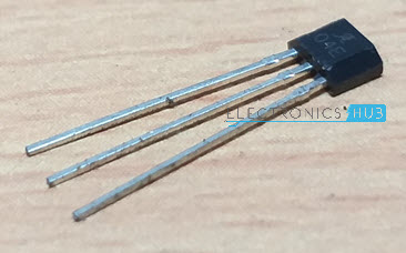
Above image shows the A1104 Hall Effect IC used in this project. It is based on BiCMOS technology, which combines the benefits of both the Bipolar and CMOS technologies.
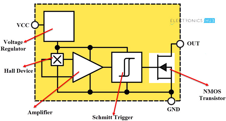
Block Diagram of the Hall Effect Sensor
The main components of the A1104 Hall Effect IC are: Voltage Regulator, Hall Device, Small Signal Amplifier, Schmitt Trigger and an Output NMOS Transistor. The following image shows the block diagram of this Hall Effect IC.
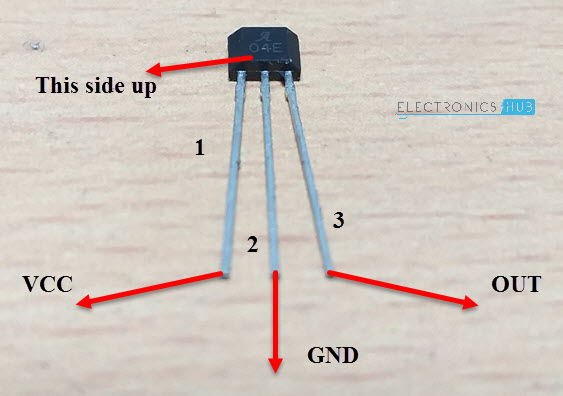
Pins of A1104 Hall Effect Sensor
Before going to see the working of a Hall Effect IC, let me give an overview of the Pins of the A1104 Hall Effect IC. There are three pins on the A1104 Hall Effect IC: VCC, GND and OUT.
- VCC (1): Power Supply to IC. 3.8V to 24V.
- GND (2): Ground.
- OUT (3): Output of the IC.
The following image shows the Pins of the A1104 Hall Effect IC.
Working of the Hall Effect Sensor
The Hall Element or the Hall Device (sometimes called as the Active Area) is a small semiconductor sheet. This is represented as the following image.
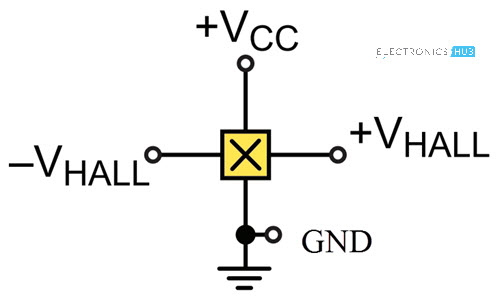
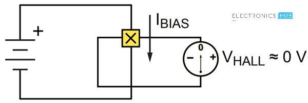
When a constant voltage is given at VCC, some small but constant current flows through the semiconductor sheet. When there is no magnetic field, the voltage VHALL, which is measured across the width of the Hall Element (semiconductor sheet) will be approximately equal to 0V.
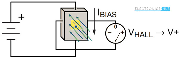
If the Hall Element is subjected to a magnetic field such that, the magnetic flux of the magnetic field is perpendicular to the current flowing through the sheet, the output voltage VHALL is directly proportional to the strength of the magnetic field.
Types of Hall Devices
Based on the orientation and characteristics of the Active Area (Hall Element), Hall Effect Sensors can be categorized into three types.
- Planar Hall Device
- Vertical Hall Device
- 3D Hall Device
In Planar Hall Devices, the flux lines of the magnetic field must pass perpendicularly through the active area to optimally operate the switch. Here, the active area is parallel to the branded face of the IC i.e. the face marked with Manufacturer part number.
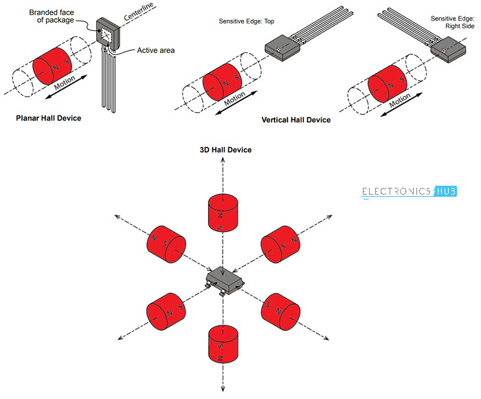
Coming to the Vertical Hall Device, its sensitive areas can be on the top edge, right side edge or left side edge. Finally, a 3D Hall Device can detect the magnetic field when the magnet is approached from any direction.
NOTE: An important point to remember about the operation of the Hall Effect Sensor is that both the magnetic field strength as well as the polarity (North or South) are equally important. The Hall Effect Sensor will switch only if it is subjected a sufficient magnetic flux density as well correct polarity.
A Hall Effect Sensor can be sensitive to either North Pole or South Pole but not both.
Interfacing Hall Effect Sensor with Arduino
Now that we have seen a little bit about the Hall Effect Sensor, let me take you through the steps of interfacing a Hall Effect Sensor with Arduino.
As usual, I will implement two circuits: one is the basic hook-up guide of Hall Effect Sensor with Arduino and the second one is an application circuit where I will control a relay with the help of Hall Effect Sensor and Arduino.
Components Required
The components required for both these circuits are mentioned below.
- Arduino UNO
- A1104 Hall Effect IC
- 10KΩ Resistor
- LED
- 1KΩ Resistor
- 5V Relay Module
- Mini Breadboard
- Connecting Wires
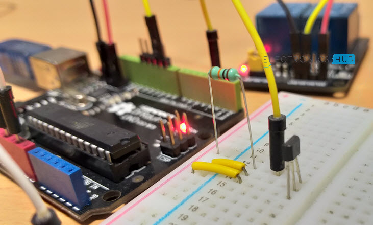
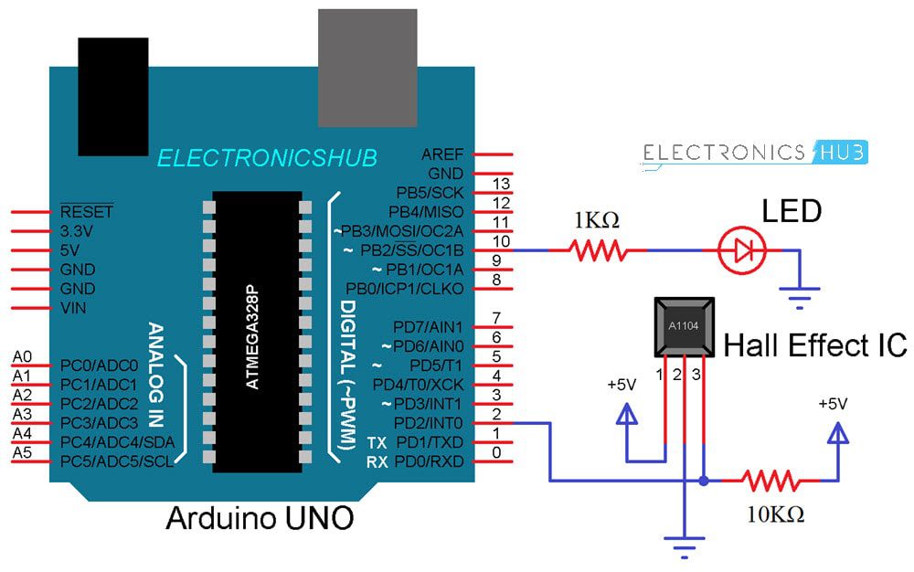
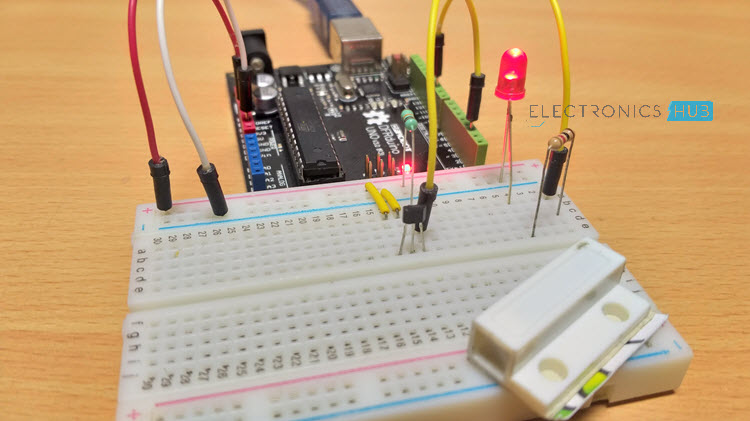
Hook-up Guide of Hall Effect Sensor with Arduino
The following image shows the necessary connections between Arduino UNO and A1104 Hall Effect IC.
Code
Working
If you notice the circuit diagram, the connections are pretty straight forward. The VCC and GND pins of the Hall Effect IC i.e. Pins 1 and 2 from the branding face are connected to +5V and GND of Arduino.
The OUT pin of the Hall Effect IC is pulled HIGH using a 10KΩ Resistor.
Whenever the magnetic field is placed near the Hall Effect IC, the output of the Hall Effect IC becomes LOW. This change is detected by Arduino and accordingly it activates the LED.
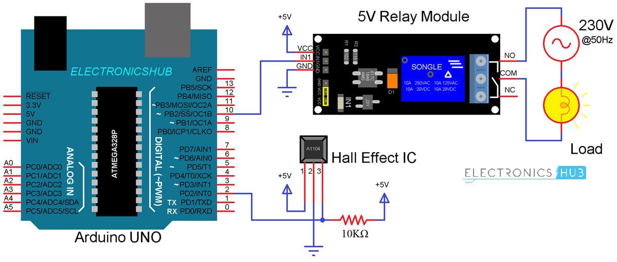
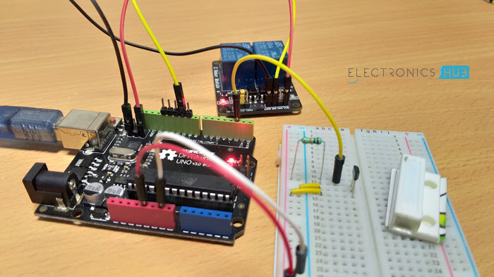
Control a Relay with Arduino and Hall Effect Sensor
The circuit diagram for controlling a 5V Relay Module with Hall Effect Sensor and Arduino is shown below.
Code
Working
The working of this circuit is very simple. Whenever the Hall Effect Sensor is subjected to a magnetic field, it toggles the Relay (as per the code).
Applications of Hall Effect Sensor
Hall Effect Sensor is used in a wide range of applications like
- Automobile ignition systems
- Tachometers
- Current Sensors
- Brushless DC Motor Controllers
- Speed Control Systems
- Printers
- Keyboards
- Switches (key and push button)
- Security Systems
- Position Detectors
The post How to use Hall Effect Sensor with Arduino? appeared first on Electronics Hub.
from Electronics Hub https://ift.tt/2uVyLNe
Friday, 27 July 2018
Latest Wireless Standards and Their Applications
 With newer technologies like 5G and IoT, standardisation becomes necessary for the devices to communicate with each other. Let us explore the latest wireless standards in detail along with their applications. The cool quotient of communication devices is increasing immensely as we advance towards newer wireless means for connectivity. The need to update benchmarks for […]
The post Latest Wireless Standards and Their Applications appeared first on Electronics For You.
from Electronics For You https://ift.tt/2Ae9O4L
Thursday, 26 July 2018
When fashion meets AI
 AI programs are becoming an efficient assistant for human stylists. These can handle more attributes, process large amounts of data faster and learn users’ styles more accurately Among all the domains of human creativity, human fashion behaviour modelling is one of the biggest challenges given its random nature due to erratic irrationality, individual uniqueness, craziness […]
The post When fashion meets AI appeared first on Electronics For You.
from Electronics For You https://ift.tt/2A7TXEM
4x4x4 RGB LED Cube
 This article describes how to build a 4x4x4 RGB LED CUBE (Fig. 6) that is controlled by Arduino. Cube construction We need 64 common cathode RGB LEDs for our cube. Test all LEDs before soldering. Bend all the leads out 90 degrees apart as shown in fig.2. Now construct a jig as shown in fig. […]
The post 4x4x4 RGB LED Cube appeared first on Electronics For You.
from Electronics For You https://ift.tt/2JWDtix
IoT Power Tracker for Your Home
![]() The power tracker is an IOT based device that helps us to keep track of our power consumption. It also alerts us when we are exceeding the power usage limit. With this device, we don’t have to wait until the end of the month to know our power usage. Daily usage alert helps us control […]
The power tracker is an IOT based device that helps us to keep track of our power consumption. It also alerts us when we are exceeding the power usage limit. With this device, we don’t have to wait until the end of the month to know our power usage. Daily usage alert helps us control […]
The post IoT Power Tracker for Your Home appeared first on Electronics For You.
from Electronics For You https://ift.tt/2LMlihd
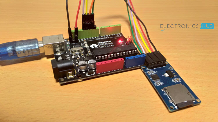
Arduino SD Card Module Interface – Hook-up Guide and Data Logging
In this project, I will show you what is an SD Card Module, how to interface a MicroSD Card Adapter with Arduino and how the Arduino SD Card Module Interface can be used for Data Logging of sensor data.
Introduction
We have interfaced several sensors like Humidity, Temperature, RTC Clock, etc. with Arduino in several earlier projects. All we did in those projects is hook-up a sensor with Arduino and view the sensor’s data on either an LCD or the Arduino IDE’s Serial Monitor.
As soon as you power-off the Arduino, all the previous data read from the sensor is lost and there is now way you can retrieve that data.
Data Logging is a process of recording data based on time or an event. Data Logging is already being implemented in several applications like Weather (Temperature), Agriculture (Soil Moisture), Automobiles (Crash Data), Aircrafts (Black Box), etc.
In our case, if we want to record the data from a sensor using Arduino, we have to interface an SD Card with Arduino. In order to do that, you have to use a MicroSD Card Adapter or an SD Card Module and understand about the Arduino SD Card Module Interface.
A Brief Note on SD Card Module / Adapter
A Micro SD Card is a flash based, removable memory device. It is non-volatile memory and is often used in mobile phones and other consumer electronic devices.
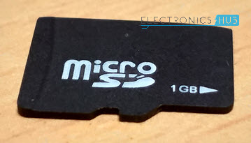
Before going to look at the SD Card Adapter, you need to understand two things about a typical Micro SD Card.
First thing is the operating voltage. Almost all Micro SD Cards work in a voltage range of 2.7V to 3.6V (typically, 3.3V). Second, is the communication interface. A Micro SD card supports SPI Communication.
Related Post: Basics of SPI Communication
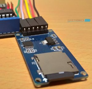
An SD Card Module or a Micro SD Card Adapter is a simple board which facilitates connection between a Micro SD card and a Microcontroller like Arduino. The following is the image of a typical SD Card Module.
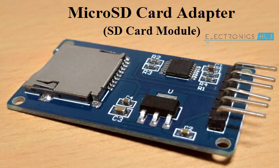
Since Arduino operates at 5V and the Micro SD Card operates at 3.3V, a typical Micro SD Card Adapter or an SD Card Module basically consists of two important components. They are the 3.3V Voltage Regulator IC and a 5V to 3.3V Level Converter IC for the communication pins.
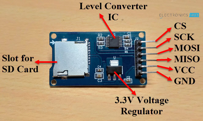
Pins of SD Card Module
Talking about pins, as I have mentioned that a Micro SD Card supports only SPI Communication, the SD Card Module has pins for SPI Communication. So, the pins on an SD Card Module are as follows.
- VCC – 5V
- GND – GND
- MOSI – Master OUT Slave IN (Input)
- MISO – Master IN Slave OUT (Output)
- SCK – SPI Clock (Input)
- CS – Chip Select (Input)
The following image shows the pins and components of an SD Card Module.
Arduino SD Card Module Interface
Now that we have seen a little bit about the SD Card Module, let us proceed with interfacing one with Arduino. First thing to remember is that the communication between Arduino and the SD Card Module is through SPI Interface.
Hence, you have to identify the SPI Pins on your Arduino Board. In case of Arduino UNO, the SPI Pins are as follows:
- MOSI – 11
- MISO – 12
- SCK – 13
- CS or SS – 10
If you are using Arduino Mega, then check for the SPI Pins before making the connection.
Coming to the Arduino SD Card Module Interface, I have designed two circuits for this project. In the first circuit, I have simply made the connection between the Arduino and the SD Card Module and extract the information of the card. This circuit can be considered as an Arduino SD Card Module Hook-up Guide.
In the second circuit, the magic of actual data logging happens. It is an extension to the first circuit with sensors connected to the Analog Pins of Arduino and the data from these sensors is captured on an event.
Components Required
Components mentioned here are combined for both the circuits.
- Arduino UNO
- Micro SD Card
- Micro SD Card Adapter or SD Card Module
- Push Button
- 3 x 10KΩ Potentiometers
- Connecting Wires
Arduino SD Card Module Hook-up Guide
The following image shows the circuit diagram of the Arduino SD Card Module Interface.
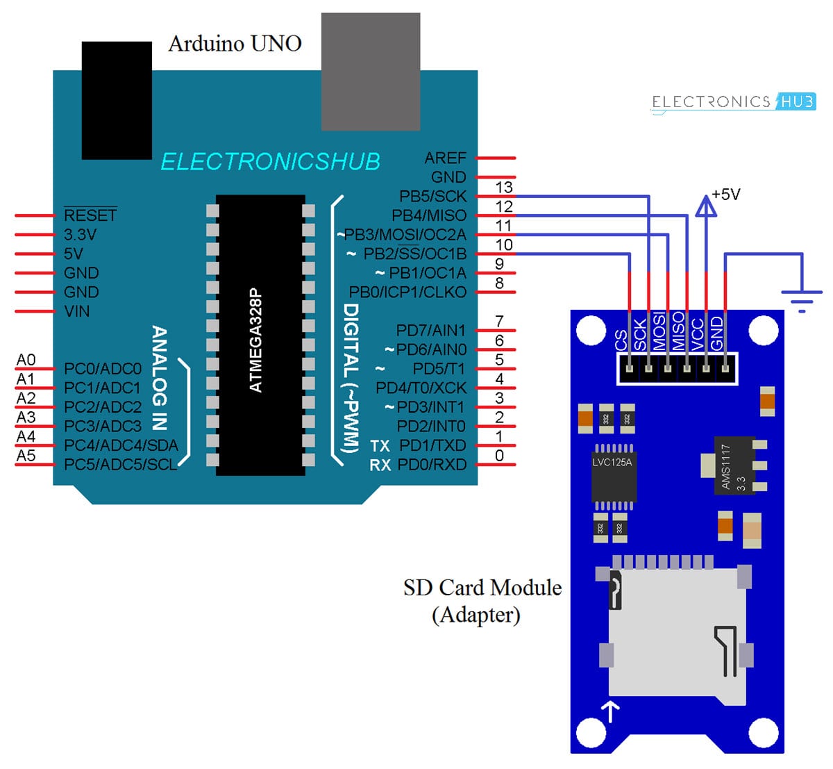
Circuit Design
Connect the MOSI, MISO, SCK and CS (SS) pins of the SD Card Module to Digital I/O Pins 11, 12, 13 and 10 of Arduino. Connect the VCC and GND pins of the SD Card Module to +5V and GND of Arduino.
Code
You can find the code in the Arduino IDE: File –> Examples –> SD –> CardInfo. You can also use the following code.
Working
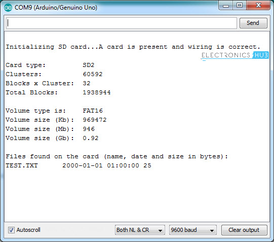
Insert a Micro SD Card in the slot provided on the SD Card Module and make the necessary connections. Upload the code to Arduino and open the Serial Monitor. If everything goes well, you can see the information about your Micro SD Card on the serial monitor.
Everything is taken care by the SPI and SD libraries of Arduino. You don’t have to download these libraries as they come with Arduino IDE.
Data Logging with Arduino SD Card Module Interface
The next circuit is about data logging on to a Micro SD Card using the Arduino and SD Card Module. The following image shows three Potentiometers connected to three Analog pins of Arduino.

Circuit Design
The Interface of Arduino and Micro SD Card Adapter is same as the earlier circuit. Additionally, three potentiometers are used as analog sensors and are connected to A0, A1 and A2 of Arduino UNO.
Also, a button is connected to Pin 7 of Arduino to mark an event.
Code
Working
As I have mentioned earlier, data logging happens either at a predefined interval of time or in case an event is triggered. For the first case i.e., to log the data based on time, you have to interface an RTC Module to Arduino and the data from the sensor can be updated to the log at a certain time interval.
Since this project is a simple interface between Arduino and Micro SD Card, I have not used an RTC Module but a simple Push Button.
When ever the button is pressed, Arduino captures the sensor data from the Analog Pins and writes them to a text file on the Micro SD Card.
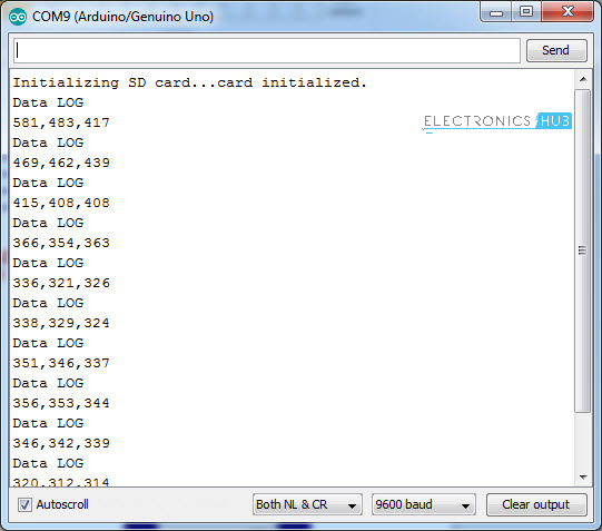
The data is also displayed on the serial monitor. To view the data, simply connect the Micro SD Card to a computer and open the text file.
IMPORTANT NOTES:
- If your Micro SD is not being read by Arduino, make sure that it is FAT formatted. The SD library supports both FAT16 and FAT32 formats.
- The SPI Pins MOSI, MISO and SCK are fixed but CS or SS pin can be modified. Make sure that you have selected the correct pin.
The post Arduino SD Card Module Interface – Hook-up Guide and Data Logging appeared first on Electronics Hub.
from Electronics Hub https://ift.tt/2Ly65DR
Wednesday, 25 July 2018
Silicon Has Replaced Many Elements Being Used Traditionally
 The advent of nanotechnology and the likes is enabling lighter, smaller and cheaper electronics. This has led to the creation of microelectromechanical systems (MEMS) oscillators. Nidhi Arora, executive editor, Electronics For You, in conversation with Rajesh Vashist, chief executive officer, SiTime, discusses the technology behind creating MEMS, the benefits these bring and their adaptability in […]
The post Silicon Has Replaced Many Elements Being Used Traditionally appeared first on Electronics For You.
from Electronics For You https://ift.tt/2v2orST
Subscribe to:
Posts (Atom)