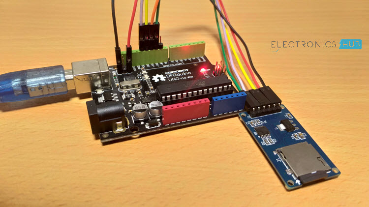
In this project, I will show you what is an SD Card Module, how to interface a MicroSD Card Adapter with Arduino and how the Arduino SD Card Module Interface can be used for Data Logging of sensor data.
Introduction
We have interfaced several sensors like Humidity, Temperature, RTC Clock, etc. with Arduino in several earlier projects. All we did in those projects is hook-up a sensor with Arduino and view the sensor’s data on either an LCD or the Arduino IDE’s Serial Monitor.
As soon as you power-off the Arduino, all the previous data read from the sensor is lost and there is now way you can retrieve that data.
Data Logging is a process of recording data based on time or an event. Data Logging is already being implemented in several applications like Weather (Temperature), Agriculture (Soil Moisture), Automobiles (Crash Data), Aircrafts (Black Box), etc.
In our case, if we want to record the data from a sensor using Arduino, we have to interface an SD Card with Arduino. In order to do that, you have to use a MicroSD Card Adapter or an SD Card Module and understand about the Arduino SD Card Module Interface.
A Brief Note on SD Card Module / Adapter
A Micro SD Card is a flash based, removable memory device. It is non-volatile memory and is often used in mobile phones and other consumer electronic devices.
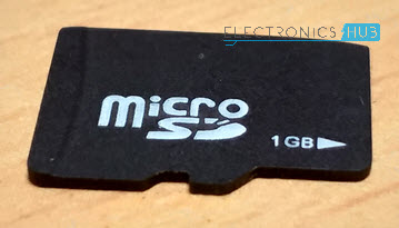
Before going to look at the SD Card Adapter, you need to understand two things about a typical Micro SD Card.
First thing is the operating voltage. Almost all Micro SD Cards work in a voltage range of 2.7V to 3.6V (typically, 3.3V). Second, is the communication interface. A Micro SD card supports SPI Communication.
Related Post: Basics of SPI Communication
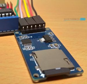
An SD Card Module or a Micro SD Card Adapter is a simple board which facilitates connection between a Micro SD card and a Microcontroller like Arduino. The following is the image of a typical SD Card Module.
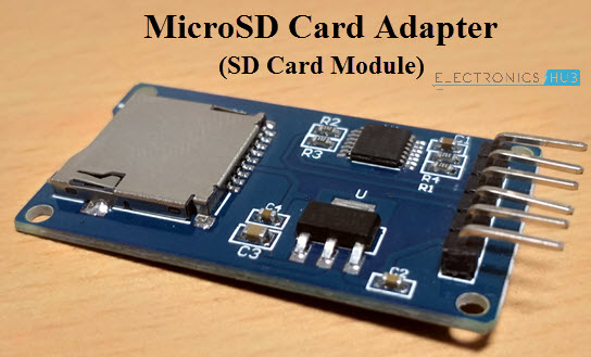
Since Arduino operates at 5V and the Micro SD Card operates at 3.3V, a typical Micro SD Card Adapter or an SD Card Module basically consists of two important components. They are the 3.3V Voltage Regulator IC and a 5V to 3.3V Level Converter IC for the communication pins.
Pins of SD Card Module
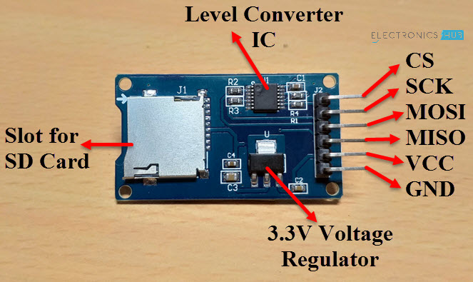
Talking about pins, as I have mentioned that a Micro SD Card supports only SPI Communication, the SD Card Module has pins for SPI Communication. So, the pins on an SD Card Module are as follows.
- VCC – 5V
- GND – GND
- MOSI – Master OUT Slave IN (Input)
- MISO – Master IN Slave OUT (Output)
- SCK – SPI Clock (Input)
- CS – Chip Select (Input)
The following image shows the pins and components of an SD Card Module.
Arduino SD Card Module Interface
Now that we have seen a little bit about the SD Card Module, let us proceed with interfacing one with Arduino. First thing to remember is that the communication between Arduino and the SD Card Module is through SPI Interface.
Hence, you have to identify the SPI Pins on your Arduino Board. In case of Arduino UNO, the SPI Pins are as follows:
- MOSI – 11
- MISO – 12
- SCK – 13
- CS or SS – 10
If you are using Arduino Mega, then check for the SPI Pins before making the connection.
Coming to the Arduino SD Card Module Interface, I have designed two circuits for this project. In the first circuit, I have simply made the connection between the Arduino and the SD Card Module and extract the information of the card. This circuit can be considered as an Arduino SD Card Module Hook-up Guide.
In the second circuit, the magic of actual data logging happens. It is an extension to the first circuit with sensors connected to the Analog Pins of Arduino and the data from these sensors is captured on an event.
Components Required
Components mentioned here are combined for both the circuits.
- Arduino UNO
- Micro SD Card
- Micro SD Card Adapter or SD Card Module
- Push Button
- 3 x 10KΩ Potentiometers
- Connecting Wires
Arduino SD Card Module Hook-up Guide
The following image shows the circuit diagram of the Arduino SD Card Module Interface.
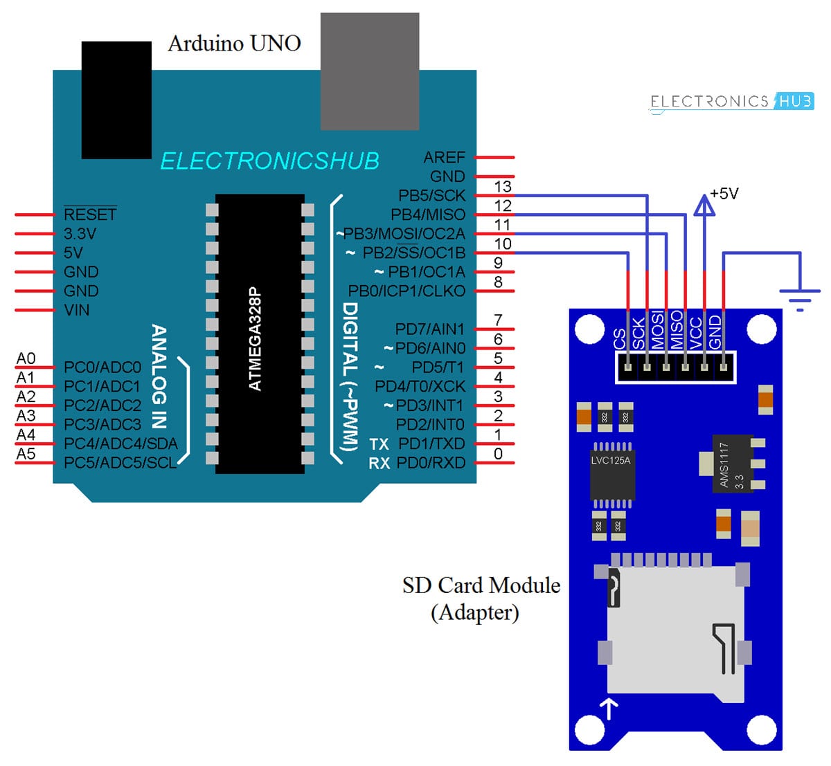
Circuit Design
Connect the MOSI, MISO, SCK and CS (SS) pins of the SD Card Module to Digital I/O Pins 11, 12, 13 and 10 of Arduino. Connect the VCC and GND pins of the SD Card Module to +5V and GND of Arduino.
Code
You can find the code in the Arduino IDE: File –> Examples –> SD –> CardInfo. You can also use the following code.
Working
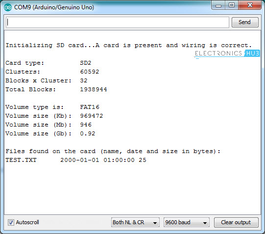
Insert a Micro SD Card in the slot provided on the SD Card Module and make the necessary connections. Upload the code to Arduino and open the Serial Monitor. If everything goes well, you can see the information about your Micro SD Card on the serial monitor.
Everything is taken care by the SPI and SD libraries of Arduino. You don’t have to download these libraries as they come with Arduino IDE.
Data Logging with Arduino SD Card Module Interface
The next circuit is about data logging on to a Micro SD Card using the Arduino and SD Card Module. The following image shows three Potentiometers connected to three Analog pins of Arduino.

Circuit Design
The Interface of Arduino and Micro SD Card Adapter is same as the earlier circuit. Additionally, three potentiometers are used as analog sensors and are connected to A0, A1 and A2 of Arduino UNO.
Also, a button is connected to Pin 7 of Arduino to mark an event.
Code
Working
As I have mentioned earlier, data logging happens either at a predefined interval of time or in case an event is triggered. For the first case i.e., to log the data based on time, you have to interface an RTC Module to Arduino and the data from the sensor can be updated to the log at a certain time interval.
Since this project is a simple interface between Arduino and Micro SD Card, I have not used an RTC Module but a simple Push Button.
When ever the button is pressed, Arduino captures the sensor data from the Analog Pins and writes them to a text file on the Micro SD Card.
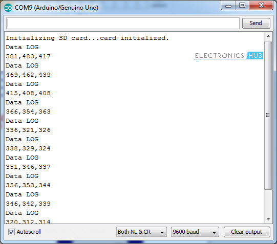
The data is also displayed on the serial monitor. To view the data, simply connect the Micro SD Card to a computer and open the text file.
IMPORTANT NOTES:
- If your Micro SD is not being read by Arduino, make sure that it is FAT formatted. The SD library supports both FAT16 and FAT32 formats.
- The SPI Pins MOSI, MISO and SCK are fixed but CS or SS pin can be modified. Make sure that you have selected the correct pin.
The post Arduino SD Card Module Interface – Hook-up Guide and Data Logging appeared first on Electronics Hub.
from Electronics Hub https://ift.tt/2Ly65DR
No comments:
Post a Comment