In this project, we will learn about TP4056 Lithium Ion Battery Charger which is based on the TP4056 Li-Ion Battery Charger IC. In the process, I will discuss the circuit diagram of the TP4056 Lithium Ion Battery Charger module, components on the module and how to connect an 18650 battery to this module and charge it.
WARNING: Working with batteries is extremely dangerous and if you are not familiar with the connections, results might be fatal. Battery might explode if wrongly used.
Introduction
Almost all the electronic devices and gadgets run on battery power now-a-days. You can find many devices like Mobile Phones, Tablets, Laptops, Cameras, etc. that run on battery.
Apart from the small devices mentioned above, Cars, Motorcycles, electric vehicles also contain battery and require a battery charger mechanism.
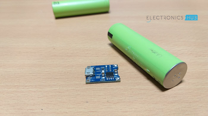
And when a battery is involved, a Battery Charger is also involved. Battery Chargers are devices that recharge the batteries by putting energy into them.
In this project, I will talk about one such battery charger module for charging Lithium Ion Batteries. It is TP4056 Li-Ion Battery Charger.
Also read: HOW TO MAKE AN AUTOMATIC BATTERY CHARGER?
A Brief Note on TP4056 Lithium Battery Charge Controller
The TP4056 is a low-cost Lithium Ion battery charger controller IC. It supports a constant current – constant voltage charging mechanism for s single cell Li-Ion Battery.
It is available in 8-pin SOP package and requires very minimum external components in order to build a Lithium Ion battery charger circuit.
Pin Diagram of TP4056 Lithium Ion Battery Charger IC
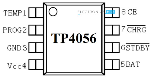
The following image shows the pin diagram of the TP4056 Li-Ion Battery Charger IC. It is an 8-pin IC and the pins are TEMP, PROG, GND, VCC, BAT, , and CE.
|
Pin Number |
Pin Name |
Function |
|
1 |
TEMP |
Temperature Sense |
|
2 |
PROG |
Constant Charge Current Setting |
|
3 |
GND |
Ground |
|
4 |
VCC |
Supply |
|
5 |
BAT |
Battery Connection Pin |
|
6 |
STDBY |
Standby Pin |
|
7 |
CHRG |
Charging Pin |
|
8 |
CE |
Chip Enable |
Pin Description
Now, let us see the description and function of each pin of TP4056 IC.
- TEMP: It is an input pin for sensing the temperature. It is connected to the output of the NTC Thermistor in a Battery Pack. Based on the voltage at this pin, you can determine the temperature of the Battery. Battery Temperature is too low if voltage is less than 45% of VCC for more than 0.15S or it is too high if voltage is more than 80% of VCC for the same duration.
- PROG: The charge current to the battery is set by connecting a Resistor called RPROG between this pin and GND. Based on the value of the resistor, the charge current can be anywhere from 130mA to 1000A.
- GND: Ground Pin.
- VCC: It is the power supply pin. TP4056 can support a maximum of 8V at VCC but typically 5V is used.
- BAT: It is the battery connection pin connected to the positive terminal of the battery. The voltage at this pin is 4.2V.
- STDBY: When the battery is completely charged, this pin is pulled low. An LED is connected to this to indicate standby mode.
- CHRG: When the battery is charging, this pin is pulled low. An LED is connected to this pin to indicate battery charging.
- CE: It is an input pin for enabling the chip into operation or disabling it. When a HIGH input is given, the TP4056 is in normal mode and when a HIGH input is given, the IC is disabled.
Controlling the Charge Current
As mentioned earlier, the PROG (Pin 2) is used to control the charge current to the battery. It is controlled with the help of a resistor called RPROG. The following table shows a list of charging current values for the corresponding RPROG values.
|
RPROG in KΩ |
IBAT in mA |
|
10 |
130 |
|
5 |
250 |
| 4 |
300 |
|
3 |
400 |
|
2 |
580 |
|
1.66 |
690 |
|
1.5 |
780 |
|
1.33 |
900 |
|
1.2 |
1000 |
This is calculated using the formula IBAT = (VPROG / RPROG) * 1200 and VPROG = 1V.
Circuit Diagram of TP4056 Lithium Ion Battery Charger
As mentioned earlier, very few external components are required for building a complete Li-Ion Battery Charger circuit using the TP4056 IC. The following image shows the circuit diagram of one such implementation.
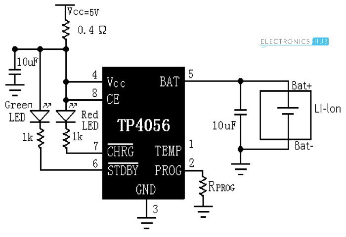
The components needed are as follows:
- TP4056 IC
- LEDs x 2
- 1KΩ Resistor x 2
- 0.4Ω Resistor
- 10µF Capacitor x 2
- 1.2KΩ Resistor (RPROG)
TP4056 Li-Ion Battery Charger Module
Based on the TP4056 Lithium Ion Battery Charger Controller IC and the above shown circuit diagram, several Li-Ion Battery Charger Modules are developed. The following image shows the module used in this project.
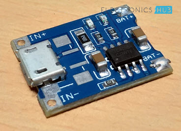
It is a tiny module with all the components mentioned in the above circuit diagram. If you notice, there is a Micro USB connector at the input side of the board. Using this, you can charge a Li-Ion battery from an USB source.
Otherwise, there are connectors for Input Voltage as well as terminals for connecting the Battery. The RPROG resistor on this module is of 1.2KΩ. Hence, this module supports a 1A (1000mA) charging current.
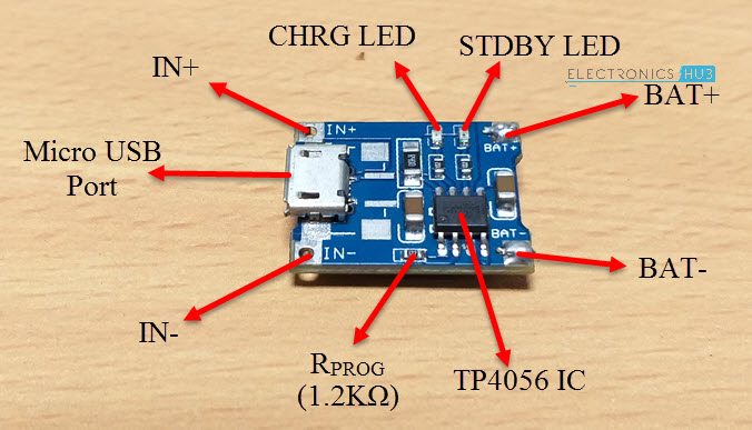
Rest of the components and parts are mentioned in the image above.
NOTE: This module and the circuit shown above doesn’t include the temperature measurement.
Charging an 18650 Lithium Ion Battery with TP4056
18650 Li-Ion batteries are very commonly found Lithium Ion batteries. They are used in Laptops, power banks, etc. I have dismantled an unused laptop battery and extracted three 18650 Batteries.
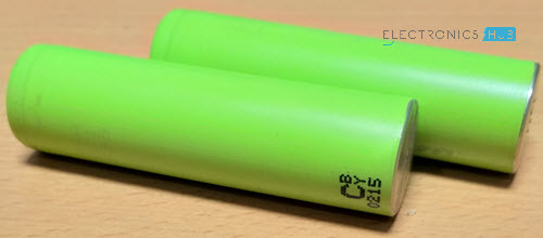
WARNING: Dismantling laptop batteries can be hazardous. We do not recommend it.
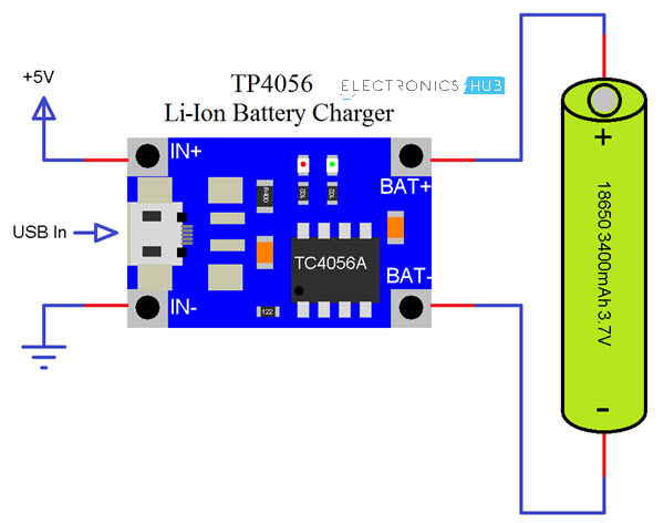
If you have 18650 Li-Ion batteries, connect one battery as shown in the following connection diagram. You can charge only one battery at a time. In order to charge the battery, you can either use the IN+ and IN- terminals and provide 5V or alternatively, you can use an USB cable to directly charge from USB supply.
Applications
TP4056 Lithium Ion Battery Charger Module (or the IC) can be used in many applications like:
- Mobile Phones
- GPS Devices
- Digital Cameras
- Power Banks
- USB Chargers
- Handheld Computers
The post TP4056 Lithium Ion Battery Charger appeared first on Electronics Hub.
from Electronics Hub https://ift.tt/2vi7nbC
No comments:
Post a Comment