Learn why you should design for rework—and 6 easy ways to do it.
from All About Circuits Technical Articles http://bit.ly/2Qz1QHY
Friday, 31 May 2019
Twice the Audio Quality at Half the Power? New Dialog Audio Codecs Offer Active Noise Canceling
Designing small audio devices with an eye for power budget? Dialog thinks it has just the codecs you need.
from All About Circuits News http://bit.ly/2EJgDLq
from All About Circuits News http://bit.ly/2EJgDLq
AVR Projects Collection | 20 ATmega MCU Projects
 AVR is a family of microcontrollers developed by Atmel beginning in 1996. These are modified Harvard architecture 8-bit RISC single-chip microcontrollers. ATmega series are one of the types of AVR microcontrollers with features like 4–256 KB program memory, 28–100-pin package, extended instruction set, and extensive peripheral set. These special features help students, hobbyists and engineers make innovative AVR projects. Let’s take a look at few interesting […]
The post AVR Projects Collection | 20 ATmega MCU Projects appeared first on Electronics For You.
from Electronics For You http://bit.ly/2Wg6ikZ
Thursday, 30 May 2019
STMicroelectronics unveils the STM32G4 series of Microcontrollers
ST's new MCUs target applications in e-mobility, digital power supplies, motor control, lighting, and building automation.
from All About Circuits News http://bit.ly/30W0R9N
from All About Circuits News http://bit.ly/30W0R9N
Real-Time Face Detection Using MATLAB
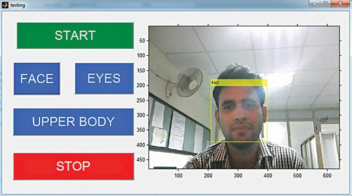 Object detection and tracking are important in many computer vision applications, including activity recognition, automotive safety and surveillance. Presented here is an face detection using MATLAB system that can detect not only a human face but also eyes and upper body. Face detection is an easy and simple task for humans, but not so for computers. […]
The post Real-Time Face Detection Using MATLAB appeared first on Electronics For You.
from Electronics For You http://bit.ly/2Wkh7CU
Working Of A Crystal Radio
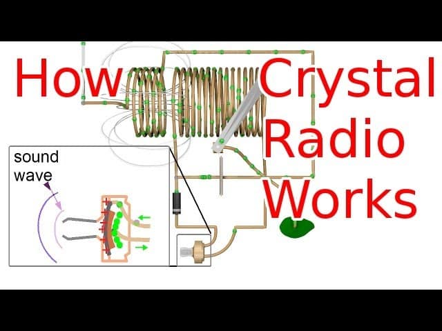 In this video, the presenter is going to explain about working of a Crystal Radio. He starts with a demonstration of all the parts in action, showing how the radio waves interact with the antenna and antenna coil to produce a fluctuating magnetic field, which induces electron flow in the tuning coil, which works with […]
The post Working Of A Crystal Radio appeared first on Electronics For You.
from Electronics For You http://bit.ly/2JMV29k
Industrial Digital Thermometer
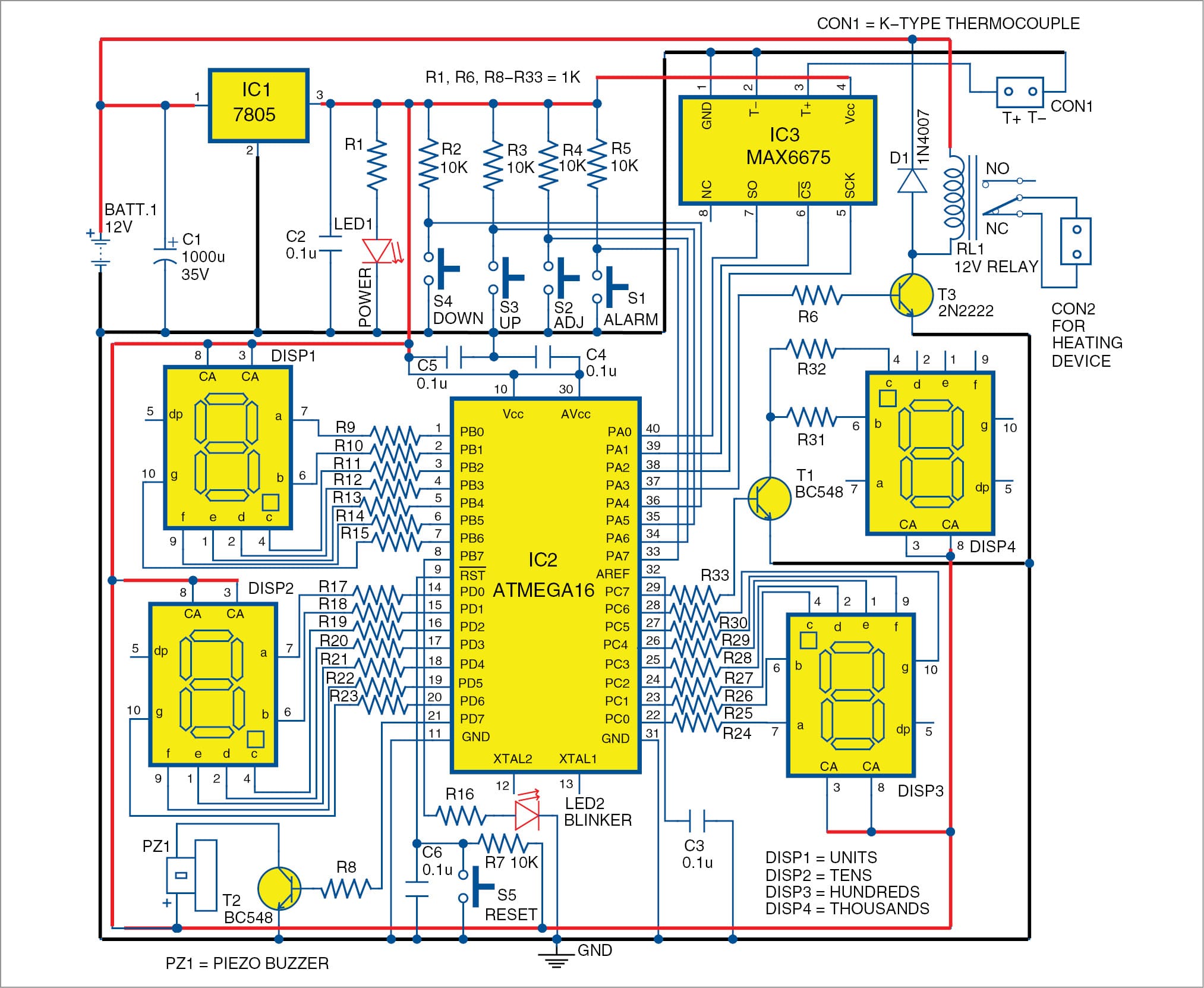 Presented here is a 4-digit Industrial Digital thermometer based on ATmega16 microcontroller (MCU), which can measure temperature up to 1024°C. Normal thermometers have a limited range, and can easily get damaged at very high temperatures. So thermocouples are used in industries for measuring very high temperatures. This circuit uses a K-type thermocouple along with MAX6675 […]
The post Industrial Digital Thermometer appeared first on Electronics For You.
from Electronics For You http://bit.ly/2MjSxNP
Best Robot Dog Toys for Kids in 2019 Reviews
Since our childhood toys played an important role in shaping our lives. They kept us entertained, helped to develop our cognitive functions, motor skills. So, if you want to purchase a toy for your baby boy or girl, you need to be sure regarding the quality of the toy.
One of the most popular type of toys are the dog toys. You can find the soft and cuddly ones in the stores but these days with the advancement of technology robot dog toys are available in the stores. These toys are amazing, a proper replacement for actual pet dogs. The almost act like the real ones and using the advance sound and visual modifications they are designed to sound and feel like real puppies.

But different manufacturers are designing them and a lot of varieties are available on the market and online shops. So, it would be quite hard for you to get the best robot puppy for your kid as there are a lot factors you need to consider like the price, quality, sound, movements and even the popularity of the manufacturer. So, there is a detailed buying guide on the factors you should look for while buying it on this article.
Also, in order to reduce the burden of searching and looking for the dog toy we have compiled a list of 10 best companion robot dog toys for you. They are detailed and listed below.
Top 10 Best Robot Dog Toys Reviews in 2019
1. Ageless Innovation Joy For All Companion Pets Golden Pup

This is called the Golden Pup, designed by Hasbro, it’s one of the best companion pet toys available on the market. It has a very simple but attractive design with a fur that looks and feels real. It also features heartbeat, the most realistic bark and life like responses. This is an amazing interactive puppy designed for comfort and convenience. According to us, this is the best interactive puppy in this list which deserved to be on the first place.
Pros
- The advanced BarkBack tech was used to makes it sound so real.
- Touch sensitive, responds to your touches accordingly like a real puppy.
- The soft and quality fur and the real-life design makes it very comfy and attractive.
- It runs on 4 C batteries which are included in the package.
Cons
- The fur quality is not so good.
- Battery runs out pretty quickly.
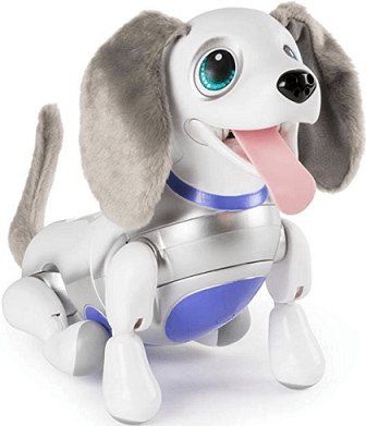
2. FurRealGoGo My Walkin’ Pup Pet

This interactive dog toy provides rich real pet like experience. This toy is engaging, exciting and creates a life-long bond with the kids. You use the leash controller to take her for a walk, you can even pet and talk to her. She responds to your voice and the movements are life-like. This Get Up&GoGo puppy is designed by FurReal and it is one of the best looking interactive robot puppy we have seen; and thus currently it is holding the 2nd position on our list.
Pros
- A very attractive robot puppy, perfect for kids.
- Comes with a remote control leash, you can take it to walk. Feels like a real pet.
- If you pet it, it sits down.
- Covered with soft fur which is very life-like.
- Sounds just like a real puppy.
Cons
- Does not have a wrist band or a remote.
- Bit over-priced.
3. Electronic Pet Dog Interactive Puppy – Robot Harry

The cuteness and functionality of this robot dog has attracted a number of customers, including us. This is the 3rd toy robot on our list and it is quite attractive. The big cute eyes of robot puppy Harry attract kids. It is a portable battery operated toy. Very durable and capable of interacting with its owner in a fun lovable way. Although the sounds are a bit below par, it makes it up with its functionalities.
Pros
- This robot dog works on most of the surfaces.
- It is equipped with Bump n Go feature.
- The robot dog harry runs on 3AA batteries.
- The sensors are touch sensitive and they are very responsive.
- The tuff plastic case provides it an extremely long life time and much wanted durability.
Cons
- Robot Harry is a bit on the expensive side.
- The sound it makes are not good at all.
4. WowWee Chippies Robot Toy Dog
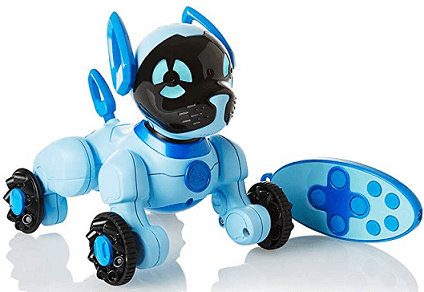
This toy robot is equipped with advanced technology and its superior design made us put it in the 4th position on your list. WowWee is a famed company known for their toy robots and Chip is their trademark product.
The design is quite different than other robot dogs, they completely threw away the idea of making it looking life-like, instead they gave it a futuristic robo-like look which is adored by kids. A remote control and an intruder alert are also added. If Chip sensed an intruder, its eyes turn red immediately and tell to stay away.
Pros
- Chip is equipped with advanced technology.
- The design is baby proof.
- Very durable.
- Addition of the intruder alert is great.
- A remote is added to control is from a distance.
Cons
- The toy has attached wheel under its 4 legs, the wheel makes constant noise which is very annoying.
5. Westminster Chi-Chi Chihuahua

The Chihuahua is a very popular breed of puppies and Westminster went straight for it. It is one of the best looking cuddly robot dog for your kids. The inside is made of plastic but the outside is coated with good quality fur that is almost life-like, making it best suited for the 5th position on our list.
It acts like a real Chihuahua too. It can move its tail, nod its head and makes cute noises. Very suitable for kids above the age of 4.
Pros
- The fur is very soft and realistic.
- Suitable for kids above the age of 4.
- Movements are very real.
- It can nod, walk and even move its tail.
Cons
- If your kid is older then, this puppy will be too small for them.
6. Little Live Pets – Rollie

The 6th position is taken by Rollie. It may not be so technologically advance but it is the cutest puppy you will ever find. It has the most amazing look, the fur is soft and it is super huggable making it one of the best choices for you.
It can kiss, cuddle and move just like a real puppy. It also makes cute puppy sounds.
Pros
- It’s cute and cuddly.
- The most huggable puppy ever.
- It licks and kiss and it is very adorable.
- It can also wag its tail and makes realistic movements.
Cons
- The build quality is not so good.
7. Fisca Remote Control Dog Programmable Robot Puppy

The 7th position is taken by the robot dog manufactured by fisca. It is an amazing intelligent and programmable robot dog that interacts with you if you just pat its head. It is great for children and its 4 dance number with music makes it so cute and attractable to our kids.
It has a very smooth and shiny surface and a power saving mode designed to preserve energy.
Pros
- The setup is very easy.
- It can dance with music, walking movement is also available.
- Remotely controllable. The remote control and its batteries are included.
- After charging it can play for an hour.
Cons
- Charging takes too long.
8. Contixo Puppy Smart Interactive Robot Pet Toy for Kids
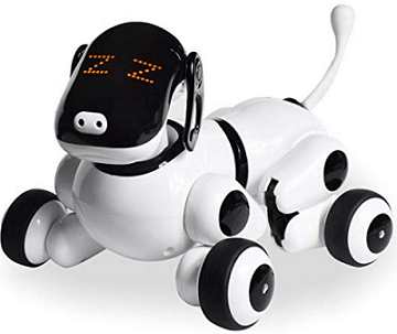
This is the smart puppy designed by Contixo. It is responsive to voice and even touch and it also comes with an app. The app control is amazing and it is integrated with quality Bluetooth speakers.
A rhythm feature is also added which makes the one of the best robotic puppies and 8th best choice on our list.
Pros
- It has a futuristic robot type look.
- If you just rub its chin, it will react.
- It is also susceptible to voice commands.
- An infrared motion sensor is also added.
- The app controlled features are amazing.
Cons
- The operation is just too complicated for the kids.
9. Zoomer responsive Robotic Dog with Voice Recognition
The playful pup by Zoomer is an ideal friend for your child. It responds to your voice and capable of learning new tricks. It has a smooth robotic body but it has pair of cute fur coated ears and a fur coated tail. This pet robot is very adorable and responds to your touch and it deserves to be at the 9th position on your list.
Needless to say, this puppy is very interactive and engaging. It will keep your kid busy for a long period of time. It barks and movements are excellent too.
Pros
- The design is outstanding and different.
- Responsive if you touch it.
- It learn ticks like “Puppy Sit” or “Lie Down”.
- It barks and begs.
Cons
- The use is too complicated.
- Not very durable.
10. Dimple Wireless Remote Control Robot Puppy
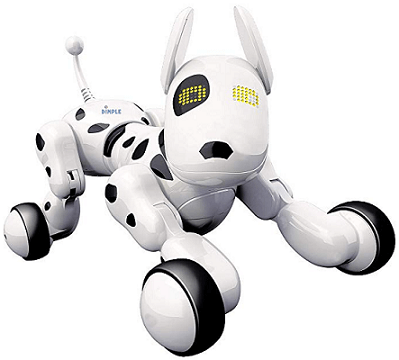
The Dimple’s wireless toy robot is very responsive to voice commands. This hi-tech interactive puppy has a sleek design and with the help of the provided remote control you can operate this puppy even from 50 meter distances. This futuristic looking robot puppy is the last product on our list due to its conveniently accessible nature.
It has an interesting design, the eyes are equipped with large LED lights which can turn into screen and display alphabets. Basically, this robot toy helps to educate your kid.
Pros
- It comes with a rechargeable battery.
- It can sing, 4 cute songs are included.
- It is designed with BPA free plastic.
- Comes with a remote control which can be used from 50 meter distance; very convenient.
Cons
- There are no additional features.
- Not very engaging.
Robot Dog Toys Buying Guide
After all you got an exclusive insight into our selection of the 10 best robot pet puppies. But it is still not enough for you to purchase the best robot pet within your price range. If you are getting a robot dog for your kid you have to learn about a few attributes in order to choose the right one. Learn about the attributes in details, below;
-
Type of Robot Toys
First, you need to decide which type of robot dog you want to get for your kid. These toys come in different sizes and different looking ones are also available. So, you need to select the one that your kid will really love to play with, if you have a toddler then you must buy a small one, it will be easier to manage. The bigger and bulkier toys are suitable for older kids. But finally, you need to check the design. It needs to be attractive or your kid won’t like it.
-
Technology
These are not just toys, the advancement and technologies are also related to it. So, you also have to think about the technology used on the toy too. Generally, most of such toys look similar but the technology used inside is completely different. So, you need to remember these things while you are buying these toys. Thoroughly check the toy, see if can move around properly, the sound it makes and even the additional features. Then, get the one that shows maximum promise.
-
Durability
Just remember that you are getting this toy for your little kid; so, it has to face a tremendous amount of abuse. They can throw it or smack it on the floor and even bite it. So, there is a big chance that it will get destroyed pretty soon but if you want to get value for your money you need to choose a model that is capable of withstanding the abuse a bit longer. You have to makes sure that material used on it are the best and there are a lot of movable parts; so, they need to be unbreakable and can take up wear and tear.
-
Safety
The safety is obviously important! They are definitely fun to play with but you also have to remember that you are going to give it to your little kid and these are electronic products. There are obviously the Chocking hazards! So, look for things that can cause it while buying it, also check the material of the fur, if it is cheap it can cause irritation or even rashes. Lastly, check the batteries as they need to be in a safe place in order to prevent accidents.
Conclusion
Toys are important and they are one of the most essential parts of your kid’s life. Hopefully, after going through this article you won’t have any problems to purchase the best interactive dog toy for your kid that fits perfectly within your price range. You can simply choose any one from the mentioned list or use the buying guide to make a different choice.
Our personal recommendation is the Ageless Innovation Joy For All Companion Pets Golden Pup. The life-like responses, heartbeat and the close to perfect bark are its USP. It also looks very real when compared to other products here. Given the price and the overall package, it is very hard to beat this product!
The post Best Robot Dog Toys for Kids in 2019 Reviews appeared first on Electronics Hub.
from Electronics Hub http://bit.ly/2QAXvnF
Wednesday, 29 May 2019
Transimpedance Amplifier Stability
Learn about how to stabilize transimpedance amplifiers or TIAs with useful examples.
from All About Circuits Technical Articles http://bit.ly/2QGhGkp
from All About Circuits Technical Articles http://bit.ly/2QGhGkp
Can We Give AI the Ability to Form Memories? The Basics of Hyperdimensional Computing
Is hyperdimensional computing the future of AI? Learn about a theory that could revolutionize machine vision.
from All About Circuits News http://bit.ly/2wsKl2W
from All About Circuits News http://bit.ly/2wsKl2W
iPaaS Connects Discrete Applications To Work As One, Thus Saving Effort And Directly Impacting The Operational Cost
 Integration platform as a service (iPaaS) enables creation and deployment of integration points to transfer data between business applications. Atul Gupta, founder and chief executive officer, InSync Tech-Fin Solutions, discusses with Deepshikha Shukla how adoption of iPaaS has changed the integration game. Q. What technologies are getting embedded with iPaaS? A. iPaaS is a suite […]
The post iPaaS Connects Discrete Applications To Work As One, Thus Saving Effort And Directly Impacting The Operational Cost appeared first on Electronics For You.
from Electronics For You http://bit.ly/2McAAAA
Tuesday, 28 May 2019
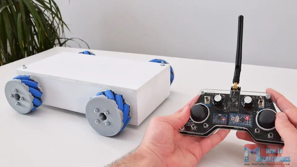
Arduino Mecanum Wheels Robot
In this tutorial we will learn how to build an Arduino Mecanum Wheels Robot which is capable of moving in any direction. This unique mobility of the robot is achieved by using special type of wheels, called Mecanum Wheels.
Overview
I actually designed and 3D printed these wheels because they can be a bit expensive to buy. They work quite well and I must say that driving this robot platform is so fun. We can wirelessly control the robot using the NRF24L01 radio transceiver modules, or in my case, I’m using my DIY RC Transmitter which I made in one of my previous videos.
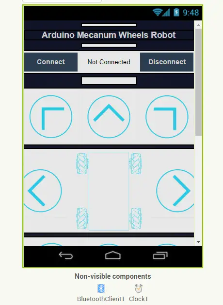
I also made it possible to be controlled using a smartphone via Bluetooth communication. I made a custom Android application through which we can control the Mecanum wheels robot to move in any direction. Also, using the slider in the app we can control the speed of movement.
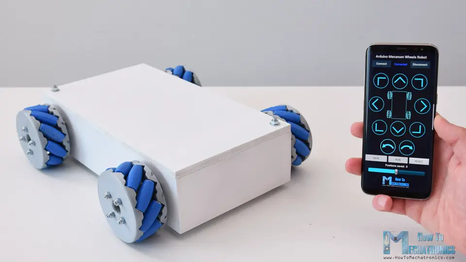
The brain of this robot platform is an Arduino Mega board which controls each wheel individually. Each wheel is attached on a NEMA 17 stepper motor, and knowing the fact that stepper motors can be precisely controlled, I added one more cool feature in the app through which we can program the robot to move automatically. Using the Save button we can save each position or step and then the robot can automatically run and repeat these steps. With the same button we can pause the automatic operation as well as reset or delete all steps so we can store new ones.
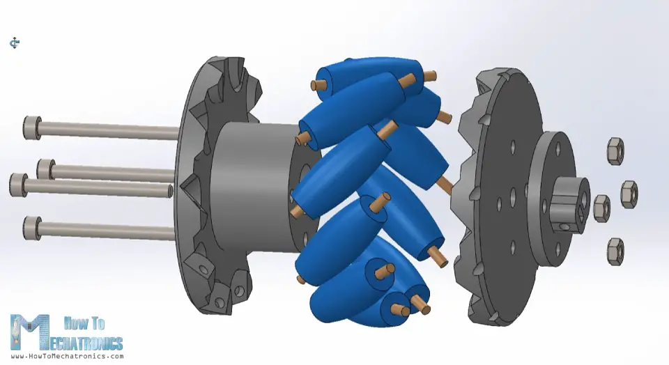
Mecanum Wheels Robot 3D Model
To begin with, I designed this Mecanum Wheels robot using a 3D modeling software. The base platform of this robot is a simple box which I will make out of 8mm tick MDF boards.
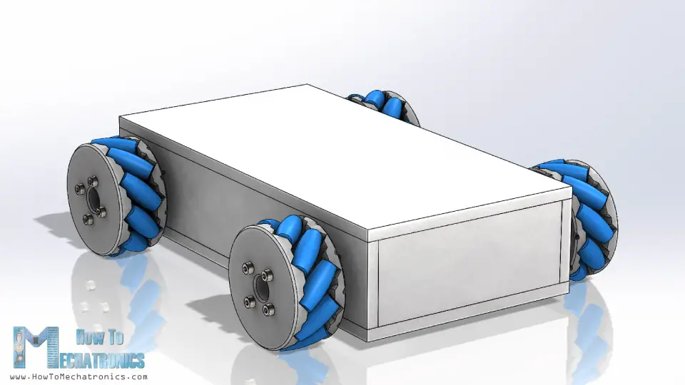
The four stepper motors are attached to this platform and the Mecanum wheels are attached to the motor’s shafts.
You can download the 3D model and the STL files needed for 3D printing below.
STEP file:
Mecanum Wheels Robot 3D Model STEP file 2.05 MB
STL files for 3D printing:
Mecanum Wheels Robot STL files 611.68 KB
How Mecanum Wheels Work
A Mecanum wheel is a wheel with rollers attached to its circumference. These rollers are positioned diagonally or at 45-degree angle to the axis of rotation of the wheel. This makes the wheel exert force in diagonal direction when moving forward of backward.
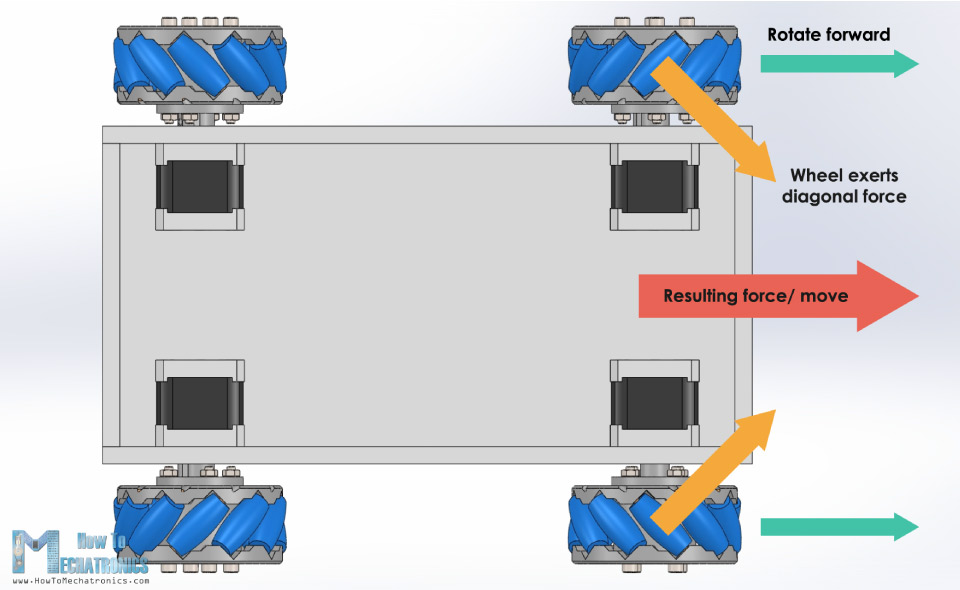
So, by rotating the wheels in certain patters, we utilize these diagonal forces and thus the robot can move in any direction.
We should also note here that we need two types of Mecanum wheels, often referred to as, left-handed and right-handed Mecanum wheels. The difference between them is the orientation of the rollers and they must be installed in the robot in specific locations. The rotation axis of each wheel’s top roller should point to the center of the robot.
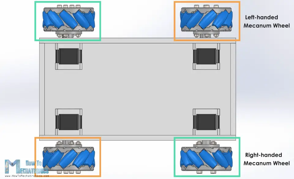
Here’s a quick demonstration of how to robot moves depending on the wheels rotation direction.
If all four wheels move forward, the resulting move of the robot will be forward, and vice versa if all wheels move backward the robot will move backward. For moving to the right, the right wheels need rotate inside the robot, while the left wheels need rotate outside the robot. The resulting force due to the diagonally positioned rollers will make the robot move to the right. The same but opposite happens when moving to the left. With these wheels we can also achieve movement in diagonal direction by rotating only two wheels.
Making the Mecanum Wheels Robot
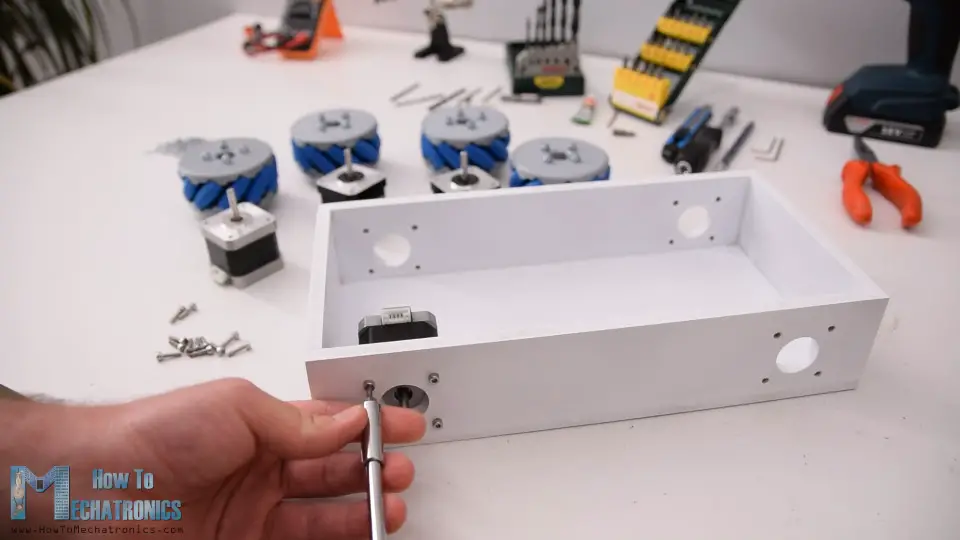
Nevertheless, now let me show you how I built this robot platform. As I mentioned, for making the base of the platform I’m using 8mm tick MDF boards. Using a table saw, first I cut all of the pieces according to the 3D model dimensions.
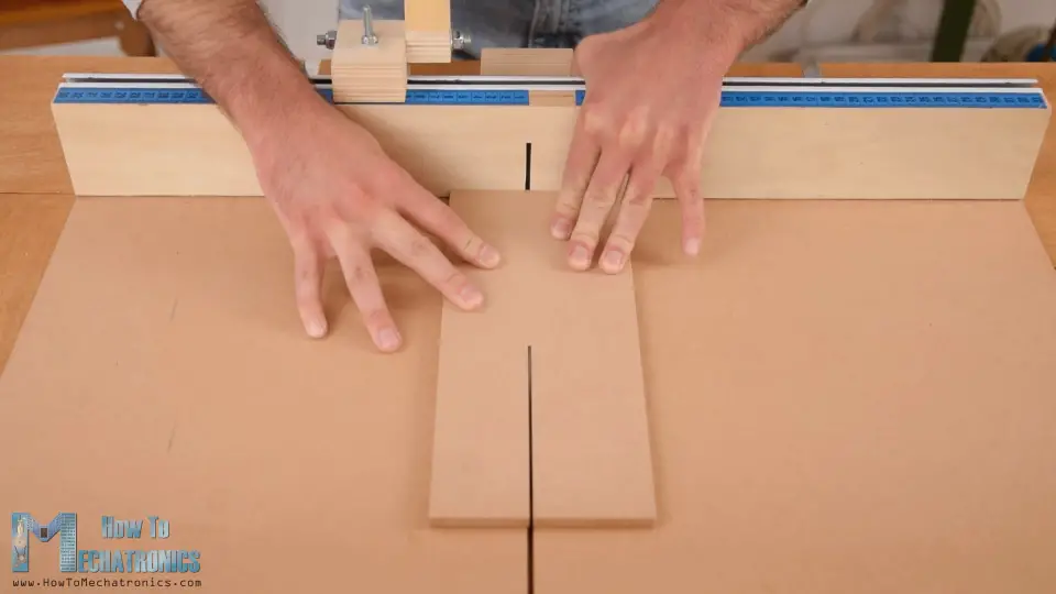
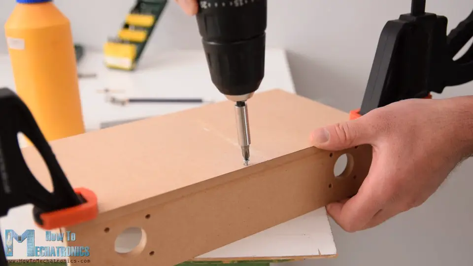
Next, using a 3mm drill and a 25mm Forstner bit I made the openings on the side panels for attaching the stepper motors. Once I got the pieces ready, I continued with assembling them. I used a wood glue and some screws for securing them. The most important thing here is to have the openings for the motors precisely made so that all of the wheels have even contact with the surface later on.
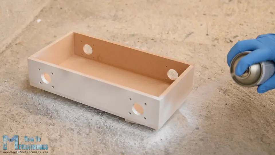
Of course, you could also 3D print this base platform, instead of making it with MDF, so I will include a 3D file of it on the website article. Finally, I spray painted the base and it’s cover with white color.
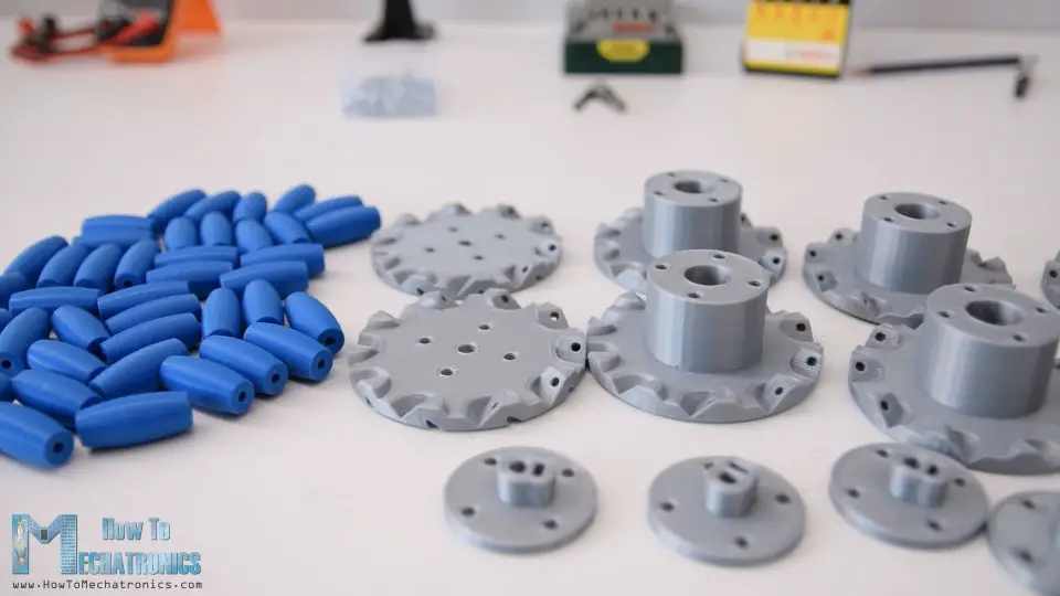
Next are the Mecanum wheels. As I said earlier, these wheels can be a bit expensive to buy, so that’s why I decided to design and 3D print my own ones. The wheels are made out of two parts, outer and inner side which are secured together with some M4 bolts and nuts. They have 10 rollers each, and a shaft coupler specifically designed to fit a NEMA 17 stepper motor.
I 3D printed all of the parts for the Mecanum wheels using my Creality CR-10 3D printer. 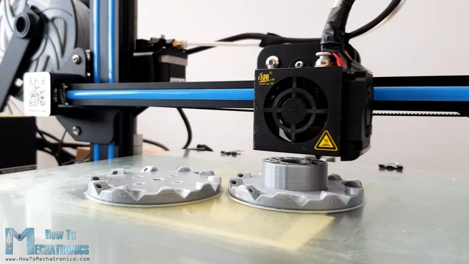
Here’s a link to this 3D printer in case you want to check it out.
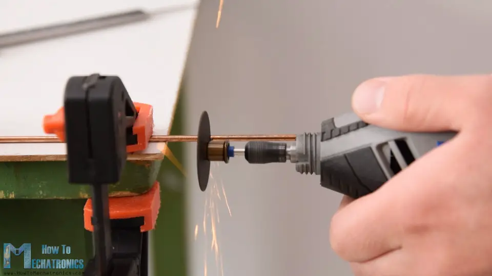
So, once I got the 3D printed parts ready, I moved on with making the shafts for the rollers. For that purpose, I used 3 mm tick steel wire. The length of the shafts needs to be around 40mm, so using a rotary tool I cut the wire to that length.
I started assembling the Mecanum wheel by securing the two sides and the shaft coupler using four M4 bolts and nuts. The length of the bolts needs to be 45mm.
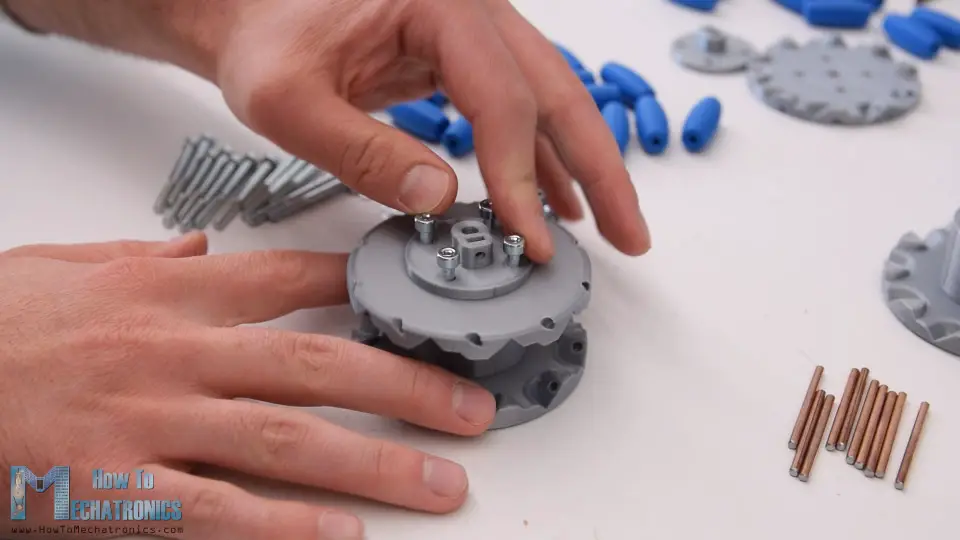
For installing the rollers, first we need to slightly insert the shaft through the holes located at the circumference of the inner side.
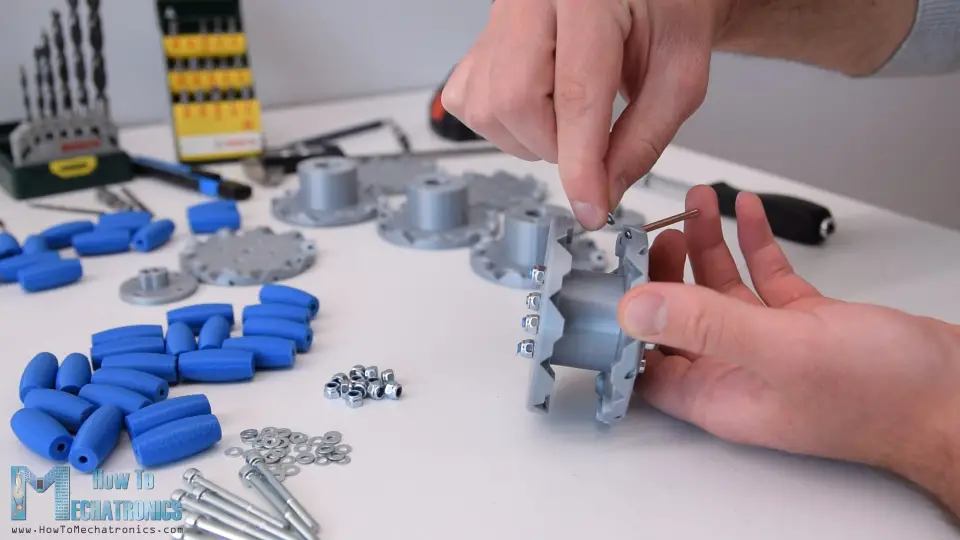
Then we can insert a small M3 washer, insert the roller and push the shaft all the way to into the slot of the outer side of the wheel. I used a single washer because I didn’t have enough space to insert a second washer on the other side.
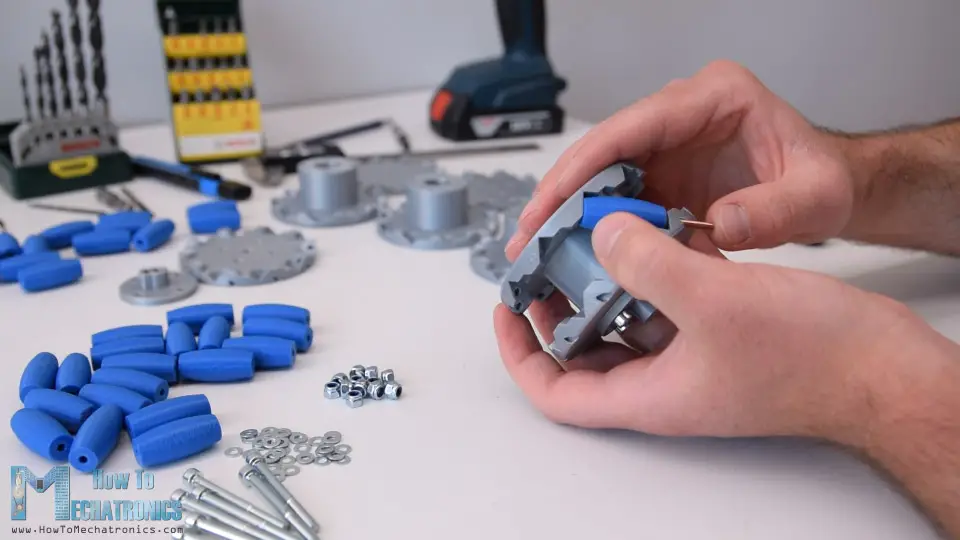
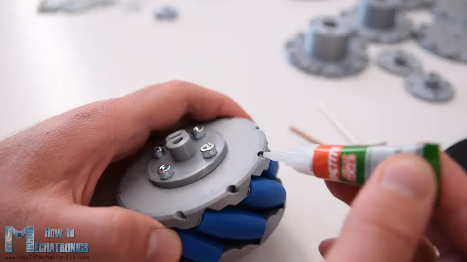
I repeated this process for all 10 rollers. It’s actually easy and kind of fun assembling these wheels. What’s important here is that the rollers need to be able to move freely.
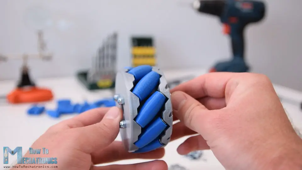
At the end I used few drops of AC glue in each of the inner holes to make sure that shafts won’t get loose.
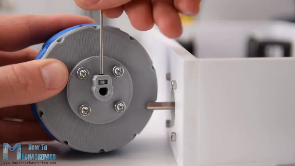
Ok so once the wheels are ready now we can move on with assembling the whole robot. First, we need to attach the stepper motors to the base platform. For securing them in place I used M3 bolts with a length of 12mm.
Next, we need to attach the wheels to the motor’s shafts. The shaft coupler that I made have a slot for inserting an M3 nut, through which an M3 bolts can pass through and so we can secure the wheel to the shaft.
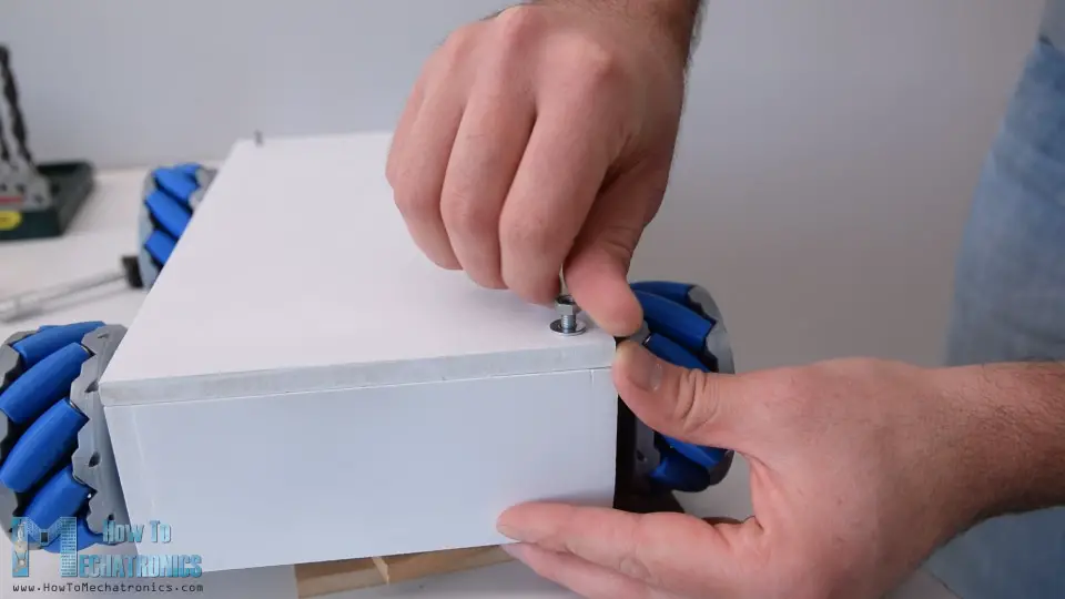
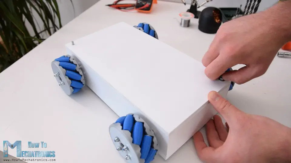
Next, for securing the top cover to the base, I attached threaded rods on two corners of the base. I made holes on the same position on the cover and so I was able to easy insert and secure the cover to the base.
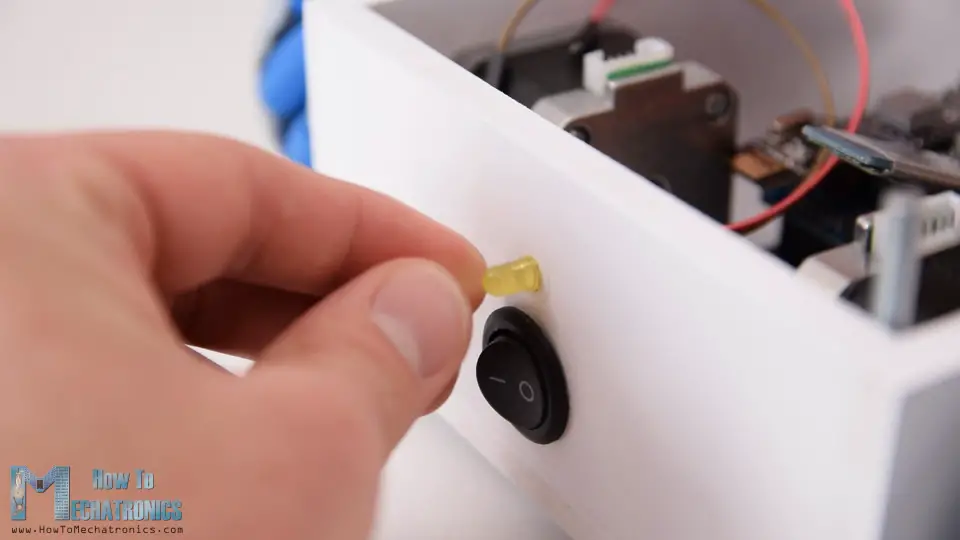
On the back side of the base I made 20mm hole for attaching a power switch later on, as well as a 5mm hole for attaching an LED.
Circuit Diagram
Now we can move on with the electronics. Here’s the complete circuit diagram of this project.
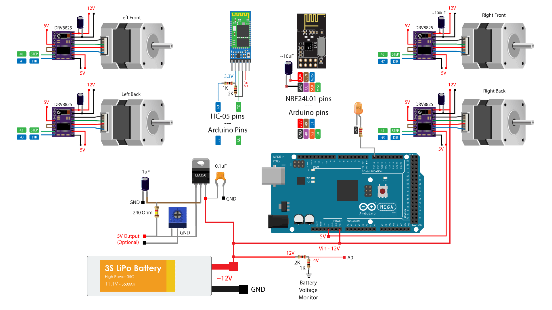
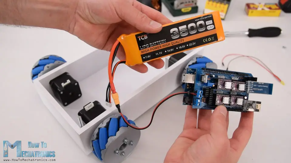
So we will control the four NEMA 17 stepper motors using four DRV8825 stepper drivers, or also we could use the A4988 stepper drivers. For powering the steppers and the whole robot we will use 12V power supply, and in my case, I will use a 3S Li-Po battery which provides around 12V. For the radio communication we are using the NRF24L01 module, and for the Bluetooth communication we are using the HC-05 Bluetooth module. I also included a simple voltage divider which will be used for monitoring the battery voltage and an LED connection for indicating when the battery voltage will drop below 11V.
I also included a dedicated 5V voltage regulator which can provide around 3A of current. This is optional, but I’m planning in a future video to combine this project with my Arduino Robot Arm project, and for that purpose I would need 5V for driving its servo motors.
ou can get the components needed for this project from the links below:
- Stepper Motor – NEMA 17……………… Amazon / Banggood
- DRV8825 Stepper Driver………………… Amazon / Banggood
- NRF24L01 Transceiver Module…….… Amazon / Banggood
- HC-05 Bluetooth Module …………….… Amazon / Banggood
- Li-Po battery …………………………….…… Amazon / Banggood
- Arduino Mega Board ………………….… Amazon / Banggood
*Please note: These are affiliate links. I may make a commission if you buy the components through these links. I would appreciate your support in this way!
PCB Design
Nevertheless, in order to keep the electronics components organized and get rid of the wiring mess, I designed a custom PCB using the EasyEDA free online circuit design software. This PCB will actually act as an Arduino MEGA shield because we will be able to directly connect it on top of the Arduino Mega board. I used both the top and the bottom layer for running the connections. For those Arduno pins which I didn’t use, I included pin header connections so that they are available in case we want to use them for something in future. I also included 12V, 5V and GND connection pins, as well as pins for selecting the stepping resolution of the drivers.
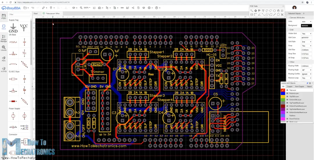
Here’s a link to the project files of this PCB design. So once I finished the design, I generated the Gerber file needed for manufacturing the PCB.
Gerber file:
Gerber File - Mecanum Wheels Robot -Arduino Mega Shield PCB 237.48 KB
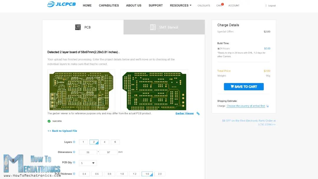
Then I ordered the PCB from JLCPCB which are also the sponsor of this video.

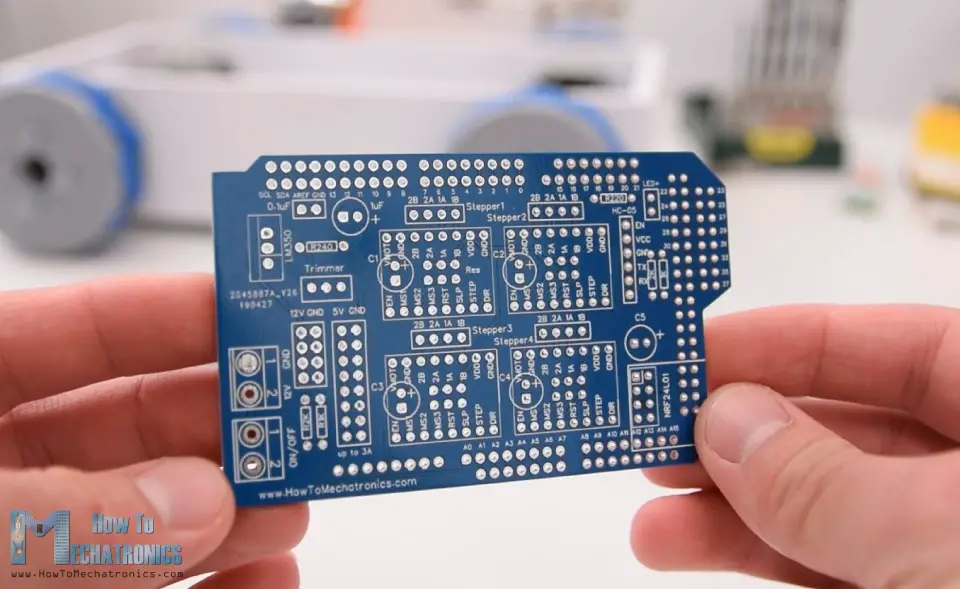
Here we can simply drag and drop the Gerber file and once uploaded, we can review our PCB in the Gerber viewer. If everything is all right then we can go on and select the properties that we want for our PCB. This time I chose the PCB color to be blue in order to match with the Arduino board color. And that’s it, now we can simply order our PCB at a reasonable price. Note that if it’s your first order from JLCPCB, you can get up to 10 PCBs for only $2.
After several days the PCBs have arrived. The quality of the PCBs is great and everything is exactly the same as in the design.
Assembling the PCB
Ok now we can move on and assemble the PCB. I started with soldering the smaller components first, the resistors and the capacitors. Then I inserted and soldered male pin headers to the PCB which will be used for connecting it to the Arduino board.
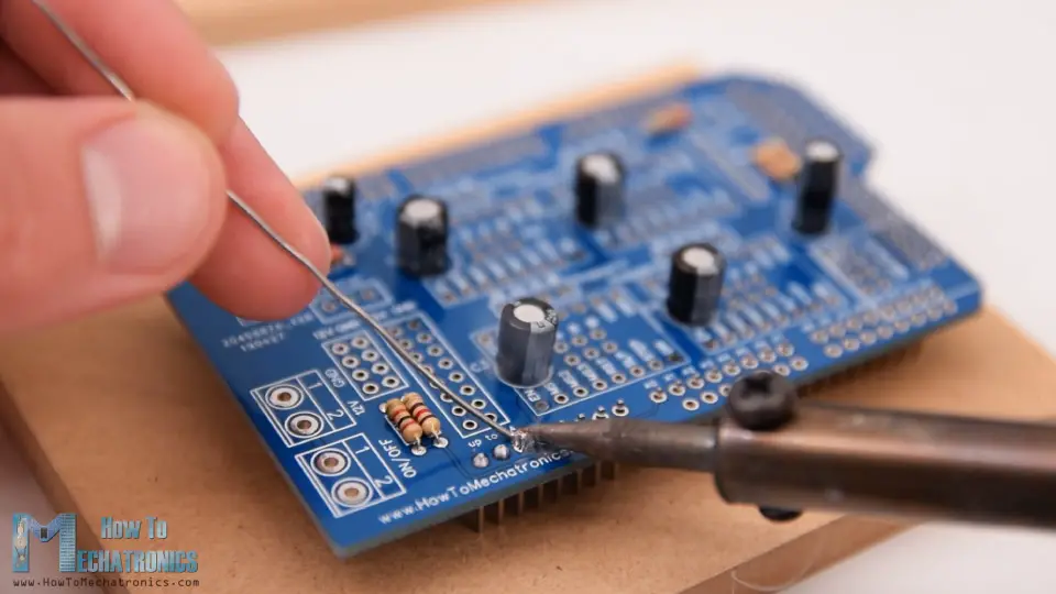
Next, I placed all female pin headers in place and soldered them as well. As for the stepper motors connections and pins for selecting the stepping resolution I used male pin headers. This way we can directly connect the motors to the PCB and use jumpers for selecting the stepping resolution. Then I soldered the terminal blocks, the trimmer and the voltage regulator.
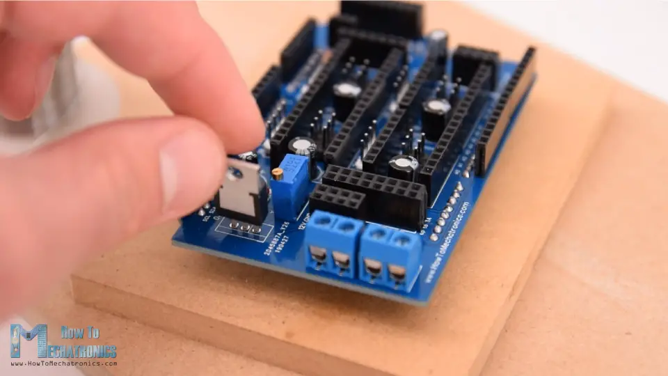
And that’s it, the PCB is now ready and we can move on with inserting the drivers and connecting the motors to it. First, I placed the jumpers for selecting the stepping resolution. I selected 16th step resolution by connecting the MS3 pins of the drivers to 5V.
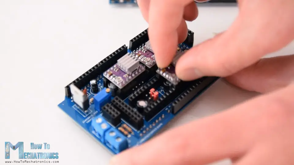
Then on top of them I placed the DRV8825 drivers, as well as, connected the NRF24L01 module and the HC-05 Bluetooth module. Now we can simple attach the PCB to the Arduno board.
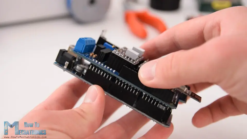
Next, I connected the battery to the appropriate terminal block and placed them into the base platform.
Here I inserted the power switch in place and connected it to the other terminal block. Right above the power switch I also inserted the battery indicator LED.
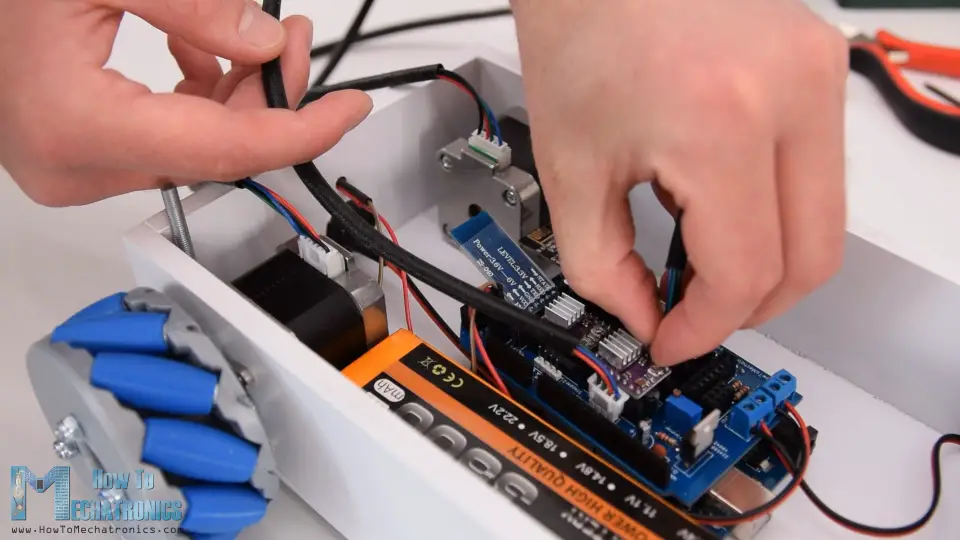
What’s left now is to connect the motors to the PCB. We should note here that when connecting opposite motors, we should connect their connectors opposite as well. This is needed later when programming the robot, so that, for example, the forward command, would move both motors in same direction, although they are actually flipped and one would make clockwise and the other anticlockwise rotation.
At the end I can simple insert the cover at the top, and so we are done with this Mecanum Wheels robot project.
Mecanum Wheels Robot Arduino Code
What’s left for this video is to take a look at the Arduino code. Actually, there are two separate Arduino codes. This one is for controlling the robot using the NRF24L01 modules and other is for controlling to robot using a smartphone.
Arduino code for controlling the robot using the NRF24L01 modules:
/*
   === Arduino Mecanum Wheels Robot ===
     Radio control with NRF24L01
  by Dejan, www.HowToMechatronics.com
  Libraries:
  RF24, https://github.com/tmrh20/RF24/
  AccelStepper by Mike McCauley: http://www.airspayce.com/mikem/arduino/AccelStepper/index.html

*/

#include <SPI.h>
#include <nRF24L01.h>
#include <RF24.h>

#include <AccelStepper.h>

RF24 radio(48, 49);   // nRF24L01 (CE, CSN)

const byte address[6] = "00001";
unsigned long lastReceiveTime = 0;
unsigned long currentTime = 0;

// Define the stepper motors and the pins the will use
AccelStepper LeftBackWheel(1, 42, 43);   // (Type:driver, STEP, DIR) - Stepper1
AccelStepper LeftFrontWheel(1, 40, 41);  // Stepper2
AccelStepper RightBackWheel(1, 44, 45);  // Stepper3
AccelStepper RightFrontWheel(1, 46, 47); // Stepper4

int wheelSpeed = 1500;

// Max size of this struct is 32 bytes - NRF24L01 buffer limit
struct Data_Package {
  byte j1PotX;
  byte j1PotY;
  byte j1Button;
  byte j2PotX;
  byte j2PotY;
  byte j2Button;
  byte pot1;
  byte pot2;
  byte tSwitch1;
  byte tSwitch2;
  byte button1;
  byte button2;
  byte button3;
  byte button4;
};
Data_Package data; //Create a variable with the above structure

void setup() {
  // Set initial seed values for the steppers
  LeftFrontWheel.setMaxSpeed(3000);
  LeftBackWheel.setMaxSpeed(3000);
  RightFrontWheel.setMaxSpeed(3000);
  RightBackWheel.setMaxSpeed(3000);

  radio.begin();
  radio.openReadingPipe(0, address);
  radio.setAutoAck(false);
  radio.setDataRate(RF24_250KBPS);
  radio.setPALevel(RF24_PA_LOW);
  radio.startListening(); //  Set the module as receiver

  Serial.begin(115200);
}

void loop() {
  // Check whether we keep receving data, or we have a connection between the two modules
  currentTime = millis();
  if ( currentTime - lastReceiveTime > 1000 ) { // If current time is more then 1 second since we have recived the last data, that means we have lost connection
    resetData(); // If connection is lost, reset the data. It prevents unwanted behavior, for example if a drone jas a throttle up, if we lose connection it can keep flying away if we dont reset the function
  }
  // Check whether there is data to be received
  if (radio.available()) {
    radio.read(&data, sizeof(Data_Package)); // Read the whole data and store it into the 'data' structure
    lastReceiveTime = millis(); // At this moment we have received the data
  }
  // Set speed - left potentiometer
  wheelSpeed = map(data.pot1, 0, 255, 100, 3000);

  if (data.j1PotX > 150) {
    moveSidewaysLeft();
  }
  else if (data.j1PotX < 100) {
    moveSidewaysRight();
  }
  else if (data.j1PotY > 160) {
    moveForward();
  }
  else if (data.j1PotY < 100) {
    moveBackward();
  }
  else if (data.j2PotX < 100 & data.j2PotY > 160) {
    moveRightForward();
  }
  else if (data.j2PotX > 160 & data.j2PotY > 160) {
    moveLeftForward();
  }
  else if (data.j2PotX < 100 & data.j2PotY < 100) {
    moveRightBackward();
  }
  else if (data.j2PotX > 160 & data.j2PotY < 100) {
    moveLeftBackward();
  }
  else if (data.j2PotX < 100) {
    rotateRight();
  }
  else if (data.j2PotX > 150) {
    rotateLeft();
  }
  else {
    stopMoving();
  }
  // Execute the steps
  LeftFrontWheel.runSpeed();
  LeftBackWheel.runSpeed();
  RightFrontWheel.runSpeed();
  RightBackWheel.runSpeed();

  // Monitor the battery voltage
  int sensorValue = analogRead(A0);
  float voltage = sensorValue * (5.0 / 1023.00) * 3; // Convert the reading values from 5v to suitable 12V i
  // If voltage is below 11V turn on the LED
  if (voltage < 11) {
    digitalWrite(led, HIGH);
  }
  else {
    digitalWrite(led, LOW);
  }
}

void moveForward() {
  LeftFrontWheel.setSpeed(wheelSpeed);
  LeftBackWheel.setSpeed(wheelSpeed);
  RightFrontWheel.setSpeed(wheelSpeed);
  RightBackWheel.setSpeed(wheelSpeed);
}
void moveBackward() {
  LeftFrontWheel.setSpeed(-wheelSpeed);
  LeftBackWheel.setSpeed(-wheelSpeed);
  RightFrontWheel.setSpeed(-wheelSpeed);
  RightBackWheel.setSpeed(-wheelSpeed);
}
void moveSidewaysRight() {
  LeftFrontWheel.setSpeed(wheelSpeed);
  LeftBackWheel.setSpeed(-wheelSpeed);
  RightFrontWheel.setSpeed(-wheelSpeed);
  RightBackWheel.setSpeed(wheelSpeed);
}
void moveSidewaysLeft() {
  LeftFrontWheel.setSpeed(-wheelSpeed);
  LeftBackWheel.setSpeed(wheelSpeed);
  RightFrontWheel.setSpeed(wheelSpeed);
  RightBackWheel.setSpeed(-wheelSpeed);
}
void rotateLeft() {
  LeftFrontWheel.setSpeed(-wheelSpeed);
  LeftBackWheel.setSpeed(-wheelSpeed);
  RightFrontWheel.setSpeed(wheelSpeed);
  RightBackWheel.setSpeed(wheelSpeed);
}
void rotateRight() {
  LeftFrontWheel.setSpeed(wheelSpeed);
  LeftBackWheel.setSpeed(wheelSpeed);
  RightFrontWheel.setSpeed(-wheelSpeed);
  RightBackWheel.setSpeed(-wheelSpeed);
}
void moveRightForward() {
  LeftFrontWheel.setSpeed(wheelSpeed);
  LeftBackWheel.setSpeed(0);
  RightFrontWheel.setSpeed(0);
  RightBackWheel.setSpeed(wheelSpeed);
}
void moveRightBackward() {
  LeftFrontWheel.setSpeed(0);
  LeftBackWheel.setSpeed(-wheelSpeed);
  RightFrontWheel.setSpeed(-wheelSpeed);
  RightBackWheel.setSpeed(0);
}
void moveLeftForward() {
  LeftFrontWheel.setSpeed(0);
  LeftBackWheel.setSpeed(wheelSpeed);
  RightFrontWheel.setSpeed(wheelSpeed);
  RightBackWheel.setSpeed(0);
}
void moveLeftBackward() {
  LeftFrontWheel.setSpeed(-wheelSpeed);
  LeftBackWheel.setSpeed(0);
  RightFrontWheel.setSpeed(0);
  RightBackWheel.setSpeed(-wheelSpeed);
}
void stopMoving() {
  LeftFrontWheel.setSpeed(0);
  LeftBackWheel.setSpeed(0);
  RightFrontWheel.setSpeed(0);
  RightBackWheel.setSpeed(0);
}


void resetData() {
  // Reset the values when there is no radio connection - Set initial default values
  data.j1PotX = 127;
  data.j1PotY = 127;
  data.j2PotX = 127;
  data.j2PotY = 127;
  data.j1Button = 1;
  data.j2Button = 1;
  data.pot1 = 1;
  data.pot2 = 1;
  data.tSwitch1 = 1;
  data.tSwitch2 = 1;
  data.button1 = 1;
  data.button2 = 1;
  data.button3 = 1;
  data.button4 = 1;
}
Descripton: So, here we are using the RF24 library for the radio communication and the AccelStepper library for controlling the stepper motors. First we need to define the pins to which all of them are connected, define some variables needed for the program below, and in the setup section set the steppers maximum speed and begin the radio communication.
In the loop section we start by reading the data coming from the RC transmitter. The RC transmitter code as well as more details how this communication works can be found on my particular tutorial for it.
So depending on the received data, for example, if the left Joystick is moved forward, its value will be greater than 160 and in such a case will call the moveForward() custom function. If we taka a look at this function we can see that all it does is it sets the speed of the motors to positive. For moving backward, the speed is set to negative. So for moving in all other directions we just have to set the rotations of the wheels appropriately as explained in the beginning.
For executing these commands, in the loop section we need to call the runSpeed() functions for all steppers. In the loop section we also read the analog input from the voltage divider coming from the battery, and according to this value we can know when the battery voltage will drop under 11V so we can turn on the indicating LED.
Arduino code for controlling to robot using a smartphone:
/*
   === Arduino Mecanum Wheels Robot ===
     Smartphone control via Bluetooth
  by Dejan, www.HowToMechatronics.com
  Libraries:
  RF24, https://github.com/tmrh20/RF24/
  AccelStepper by Mike McCauley: http://www.airspayce.com/mikem/arduino/AccelStepper/index.html

*/

#include <SoftwareSerial.h>
#include <AccelStepper.h>

SoftwareSerial Bluetooth(A8, 38); // Arduino(RX, TX) - HC-05 Bluetooth (TX, RX)

// Define the stepper motors and the pins the will use
AccelStepper LeftBackWheel(1, 42, 43);   // (Type:driver, STEP, DIR) - Stepper1
AccelStepper LeftFrontWheel(1, 40, 41);  // Stepper2
AccelStepper RightBackWheel(1, 44, 45);  // Stepper3
AccelStepper RightFrontWheel(1, 46, 47); // Stepper4

#define led 14

int wheelSpeed = 1500;

int dataIn, m;

int lbw[50], lfw[50], rbw[50], rfw[50]; // for storing positions/steps
int index = 0;

void setup() {
  // Set initial seed values for the steppers
  LeftFrontWheel.setMaxSpeed(3000);
  LeftBackWheel.setMaxSpeed(3000);
  RightFrontWheel.setMaxSpeed(3000);
  RightBackWheel.setMaxSpeed(3000);

  Serial.begin(38400);
  Bluetooth.begin(38400); // Default baud rate of the Bluetooth module
  Bluetooth.setTimeout(1);
  delay(20);

  pinMode(led, OUTPUT);

}

void loop() {
  // Check for incoming data

  if (Bluetooth.available() > 0) {
    dataIn = Bluetooth.read();  // Read the data

    if (dataIn == 0) {
      m = 0;
    }
    if (dataIn == 1) {
      m = 1;
    }
    if (dataIn == 2) {
      m = 2;
    }
    if (dataIn == 3) {
      m = 3;
    }
    if (dataIn == 4) {
      m = 4;
    }
    if (dataIn == 5) {
      m = 5;
    }
    if (dataIn == 6) {
      m = 6;
    }
    if (dataIn == 7) {
      m = 7;
    }
    if (dataIn == 8) {
      m = 8;

    }
    if (dataIn == 9) {
      m = 9;
    }
    if (dataIn == 10) {
      m = 10;
    }
    if (dataIn == 11) {
      m = 11;
    }

    if (dataIn == 12) {
      m = 12;
    }
    if (dataIn == 14) {
      m = 14;
    }
    // Set speed
    if (dataIn >= 16) {
      wheelSpeed = dataIn * 10;
      Serial.println(wheelSpeed);
    }
  }
  if (m == 4) {
    moveSidewaysLeft();
  }
  if (m == 5) {
    moveSidewaysRight();
  }
  if (m == 2) {
    moveForward();
  }
  if (m == 7) {
    moveBackward();
  }
  if (m == 3) {
    moveRightForward();
  }
  if (m == 1) {
    moveLeftForward();
  }
  if (m == 8) {
    moveRightBackward();
  }
  if (m == 6) {
    moveLeftBackward();
  }
  if (m == 9) {
    rotateLeft();
  }
  if (m == 10) {
    rotateRight();
  }

  if (m == 0) {
    stopMoving();
  }
  //Serial.println(dataIn);
  // If button "SAVE" is pressed
  if (m == 12) {
    if (index == 0) {
      LeftBackWheel.setCurrentPosition(0);
      LeftFrontWheel.setCurrentPosition(0);
      RightBackWheel.setCurrentPosition(0);
      RightFrontWheel.setCurrentPosition(0);
    }
    lbw[index] = LeftBackWheel.currentPosition();  // save position into the array
    lfw[index] = LeftFrontWheel.currentPosition();
    rbw[index] = RightBackWheel.currentPosition();
    rfw[index] = RightFrontWheel.currentPosition();
    index++;                        // Increase the array index
    m = 0;
  }

  if (m == 14) {
    runSteps();
    if (dataIn != 14) {
      stopMoving();
      memset(lbw, 0, sizeof(lbw)); // Clear the array data to 0
      memset(lfw, 0, sizeof(lfw));
      memset(rbw, 0, sizeof(rbw));
      memset(rfw, 0, sizeof(rfw));
      index = 0;  // Index to 0
    }
  }

  LeftFrontWheel.runSpeed();
  LeftBackWheel.runSpeed();
  RightFrontWheel.runSpeed();
  RightBackWheel.runSpeed();

  // Monitor the battery voltage
  int sensorValue = analogRead(A0);
  float voltage = sensorValue * (5.0 / 1023.00) * 3; // Convert the reading values from 5v to suitable 12V i
  //Serial.println(voltage);
  // If voltage is below 11V turn on the LED
  if (voltage < 11) {
    digitalWrite(led, HIGH);
  }
  else {
    digitalWrite(led, LOW);
  }

}

void runSteps() {
  for (int i = index - 1; i >= 0; i--) { // Run through all steps(index)
    LeftFrontWheel.moveTo(lfw[i]);
    LeftFrontWheel.setSpeed(wheelSpeed);
    LeftBackWheel.moveTo(lbw[i]);
    LeftBackWheel.setSpeed(wheelSpeed);
    RightFrontWheel.moveTo(rfw[i]);
    RightFrontWheel.setSpeed(wheelSpeed);
    RightBackWheel.moveTo(rbw[i]);
    RightBackWheel.setSpeed(wheelSpeed);

    while (LeftBackWheel.currentPosition() != lbw[i] & LeftFrontWheel.currentPosition() != lfw[i] & RightFrontWheel.currentPosition() != rfw[i] & RightBackWheel.currentPosition() != rbw[i]) {
      LeftFrontWheel.runSpeedToPosition();
      LeftBackWheel.runSpeedToPosition();
      RightFrontWheel.runSpeedToPosition();
      RightBackWheel.runSpeedToPosition();

      if (Bluetooth.available() > 0) {      // Check for incomding data
        dataIn = Bluetooth.read();
        if ( dataIn == 15) {           // If button "PAUSE" is pressed
          while (dataIn != 14) {         // Wait until "RUN" is pressed again
            if (Bluetooth.available() > 0) {
              dataIn = Bluetooth.read();
              if ( dataIn == 13) {
                stopMoving();
                break;
              }
            }
          }
        }
        if (dataIn >= 16) {
          wheelSpeed = dataIn * 10;
          dataIn = 14;
        }
        if ( dataIn == 13) {
          break;
        }
      }
    }
  }
  // Go back through steps
  for (int i = 1; i <= index - 1; i++) { // Run through all steps(index)

    LeftFrontWheel.moveTo(lfw[i]);
    LeftFrontWheel.setSpeed(wheelSpeed);
    LeftBackWheel.moveTo(lbw[i]);
    LeftBackWheel.setSpeed(wheelSpeed);
    RightFrontWheel.moveTo(rfw[i]);
    RightFrontWheel.setSpeed(wheelSpeed);
    RightBackWheel.moveTo(rbw[i]);
    RightBackWheel.setSpeed(wheelSpeed);

    while (LeftBackWheel.currentPosition() != lbw[i]& LeftFrontWheel.currentPosition() != lfw[i] & RightFrontWheel.currentPosition() != rfw[i] & RightBackWheel.currentPosition() != rbw[i]) {

      LeftFrontWheel.runSpeedToPosition();
      LeftBackWheel.runSpeedToPosition();
      RightFrontWheel.runSpeedToPosition();
      RightBackWheel.runSpeedToPosition();
      //Serial.print("  current: ");
      //Serial.println(LeftBackWheel.currentPosition());

      if (Bluetooth.available() > 0) {      // Check for incomding data
        dataIn = Bluetooth.read();
        if ( dataIn == 15) {           // If button "PAUSE" is pressed
          while (dataIn != 14) {         // Wait until "RUN" is pressed again
            if (Bluetooth.available() > 0) {
              dataIn = Bluetooth.read();
              if ( dataIn == 13) {
                stopMoving();
                break;
              }
            }
          }
        }
        if (dataIn >= 16) {
          wheelSpeed = dataIn * 10;
          dataIn = 14;
        }
        if ( dataIn == 13) {
          //Serial.println("DEKI");
          break;
        }
      }
    }
  }
}

void moveForward() {
  LeftFrontWheel.setSpeed(wheelSpeed);
  LeftBackWheel.setSpeed(wheelSpeed);
  RightFrontWheel.setSpeed(wheelSpeed);
  RightBackWheel.setSpeed(wheelSpeed);
}
void moveBackward() {
  LeftFrontWheel.setSpeed(-wheelSpeed);
  LeftBackWheel.setSpeed(-wheelSpeed);
  RightFrontWheel.setSpeed(-wheelSpeed);
  RightBackWheel.setSpeed(-wheelSpeed);
}
void moveSidewaysRight() {
  LeftFrontWheel.setSpeed(wheelSpeed);
  LeftBackWheel.setSpeed(-wheelSpeed);
  RightFrontWheel.setSpeed(-wheelSpeed);
  RightBackWheel.setSpeed(wheelSpeed);
}
void moveSidewaysLeft() {
  LeftFrontWheel.setSpeed(-wheelSpeed);
  LeftBackWheel.setSpeed(wheelSpeed);
  RightFrontWheel.setSpeed(wheelSpeed);
  RightBackWheel.setSpeed(-wheelSpeed);
}
void rotateLeft() {
  LeftFrontWheel.setSpeed(-wheelSpeed);
  LeftBackWheel.setSpeed(-wheelSpeed);
  RightFrontWheel.setSpeed(wheelSpeed);
  RightBackWheel.setSpeed(wheelSpeed);
}
void rotateRight() {
  LeftFrontWheel.setSpeed(wheelSpeed);
  LeftBackWheel.setSpeed(wheelSpeed);
  RightFrontWheel.setSpeed(-wheelSpeed);
  RightBackWheel.setSpeed(-wheelSpeed);
}
void moveRightForward() {
  LeftFrontWheel.setSpeed(wheelSpeed);
  LeftBackWheel.setSpeed(0);
  RightFrontWheel.setSpeed(0);
  RightBackWheel.setSpeed(wheelSpeed);
}
void moveRightBackward() {
  LeftFrontWheel.setSpeed(0);
  LeftBackWheel.setSpeed(-wheelSpeed);
  RightFrontWheel.setSpeed(-wheelSpeed);
  RightBackWheel.setSpeed(0);
}
void moveLeftForward() {
  LeftFrontWheel.setSpeed(0);
  LeftBackWheel.setSpeed(wheelSpeed);
  RightFrontWheel.setSpeed(wheelSpeed);
  RightBackWheel.setSpeed(0);
}
void moveLeftBackward() {
  LeftFrontWheel.setSpeed(-wheelSpeed);
  LeftBackWheel.setSpeed(0);
  RightFrontWheel.setSpeed(0);
  RightBackWheel.setSpeed(-wheelSpeed);
}
void stopMoving() {
  LeftFrontWheel.setSpeed(0);
  LeftBackWheel.setSpeed(0);
  RightFrontWheel.setSpeed(0);
  RightBackWheel.setSpeed(0);
}
Description: The other code for controlling the robot using the Android application, is very similar and works the same way. Here instead of the radio module we need to define the Bluetooth module and initialize its communication in the setup section. So again, first we read the incoming data from the smartphone or the Android app, and according to it, tell the robot in which direction to move.
If we take a look at the Android app we can see that it simply sends numbers from 0 to 15 through the Bluetooth when the buttons are pressed.
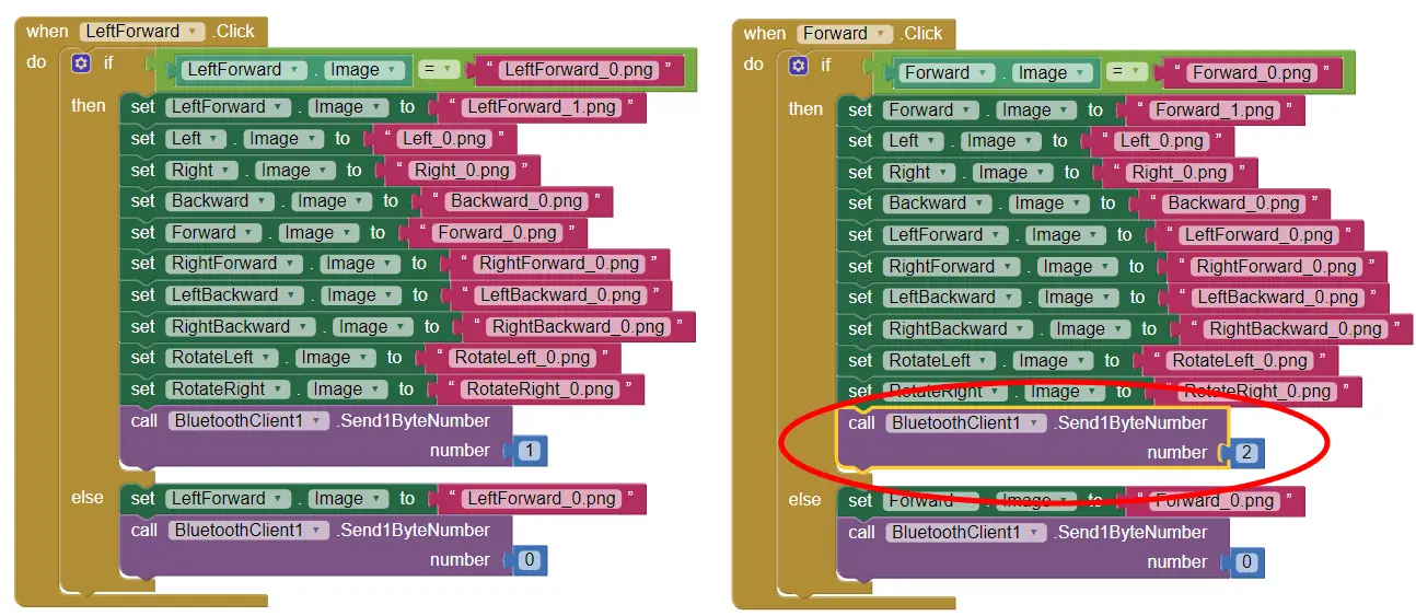
The app is made using the MIT App Inventor online application and you can find more details about it in my particular tutorial for it.
Here you can download this app as well as the editable project file:
Arduino Mecanum Wheels Robot Application Installation File 3.49 MB
Arduino Mecanum Wheels Robot Application Project File 547.84 KB
For programming the automatic robot movement with this app, when we press the “SAVE” button we simply store the current positions of the stepper motors into arrays. Then when we press the “RUN” button, we call the runSteps() custom function which executes or runs through all stored steps using some for and while loops.
I hope you enjoyed this tutorial and learned something new. Feel free to ask any question in the comments section below and check my Arduino Projects Collection.
The post Arduino Mecanum Wheels Robot appeared first on HowToMechatronics.
from HowToMechatronics http://bit.ly/2QtAjaU
Subscribe to:
Posts (Atom)