A sneak peek of two IoT platforms allows developers to save time and cost while they streamline connectivity to the cloud services.
from All About Circuits News https://ift.tt/2C6DZMo
Friday, 31 August 2018
Power Generator Forearms Machine
Download Project Document/Synopsis We hereby make use of an energy harvester system that moves in response to movement of the motion of an forearms exercise machine for converting kinetic energy of the forearms exercise equipment into electrical power. Our system makes use of the gripping rod connected to spring based motorized mechanism having rack pinion […]
from NevonProjects https://ift.tt/2PUWsyi
from NevonProjects https://ift.tt/2PUWsyi
Levitating Frictionless Vertical Windmill
Download Project Document/Synopsis In the recent year, the significance of wind generation is found to be multifold due to huge demand and supply gap in electrical energy system. Maglev wind turbines have several advantages over conventional wind turbines. For instance, they’re able to use winds with starting speeds as low as 1.5 meters per second […]
from NevonProjects https://ift.tt/2PUGzYD
from NevonProjects https://ift.tt/2PUGzYD
Kalashnikov Enters the EV Market, Highlights “Revolutionary” Inverter
What do automatic rifles and electric vehicles have in common? Kalashnikov wants to be famous for both.
from All About Circuits News https://ift.tt/2NAsqyf
from All About Circuits News https://ift.tt/2NAsqyf
Automatic Motorized Bench Vise
Download Project Document/Synopsis Vise is commonly used industrial machine tor gripping work. It plays a major part in fabrication work and is frequently used. We propose a motor operated bench vise which can tighten up to hold the work piece (as well as loosen up) by just pressing the switch. It is a motorized vice […]
from NevonProjects https://ift.tt/2CbnzSG
from NevonProjects https://ift.tt/2CbnzSG
Implementation of Shannon Fano Elias Encoding Algorithm using LabVIEW
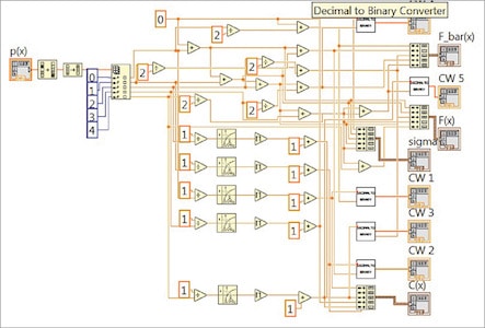 Shannon Fano Elias encoding algorithm is a precursor to arithmetic coding in which probabilities are used to determine code words. It is a lossless coding scheme used in digital communication. Probability theory has played an important role in electronics communication systems. It is because information in a signal is usually accompanied by noise. At the […]
The post Implementation of Shannon Fano Elias Encoding Algorithm using LabVIEW appeared first on Electronics For You.
from Electronics For You https://ift.tt/2MHikPu
Basic Electronic Components
If you are new to electronics or starting to build electronic circuits, then the important thing to do is to get familiar with few Basic Electronic Components and Equipment. Without understanding these basic electronic components i.e. their values, ratings, purpose etc. your circuit design might not function as expected.
There are many electronic components like Resistors, Capacitors, LEDs, Transistors, etc. and there are also many equipment like a Power Supply, Oscilloscope, Function Generator (or Signal Generator), Multimeter, etc.
In this tutorial, you can get a brief overview of few of the most common basic electronic components. For more information about a particular component, you can check out the link associated with individual component.
Basic Electronic Components
There are many ways to classify different types of electronic components but the most common way is to classify them in to three types:
1)Active Electronic Components,
2)Passive Electronic Components and
3)Electromechanical Components.
Active Electronic Components
Strictly speaking, an Active Component is a device that acts as a source of energy, like a battery. But the definition of Active Components differs according to a few electronic engineers who perform circuit analysis. Active components are defined as the devices that depend on energy source and can introduce power into a circuit.
For example consider the diode, which is an active component. When the diode is connected to the circuit and energy source is applied, it immediately does not conduct the electrons. It starts conducting only when its threshold value is reached. Thus it depends on the energy source for its working. Hence it is an active component.
Active Electronic Components can control the flow of electrons through them. Some of the commonly used Active Components are Transistors, Semiconductors(Diodes), ICs (Integrated Circuits), Power Sources (Batteries, AC and DC Power Supplies), etc.
Diodes
A diode is a non-linear semiconductor device, that allows the flow of current in one direction. A Diode is a two – terminal device and the two terminals are Anode and Cathode respectively. The following is the symbol of a Diode.
There are again a variety of components that come under the category of Diodes. They are PN Junction Diode, Light Emitting Diode (LED), Zener Diode, Schottky Diode, Photodiode, and DIAC.
Table for different types of diodes
| Diode | Application |
| GUNN Diode | Used in producing microwave signals |
| Laser Diode | Used in fiber optic communications, barcode readers ,CD/DVD drives. |
| Light emitting diode | Using lightening applications like aviation lightening, traffic signals, camera flashes. |
| Photodiode | Used as high voltage rectifier, photo detector, radio frequency switch. |
| Step recovery Diode | Used for generation and shaping of high frequency pulses. |
| Tunnel Diode | Used in microwave applications |
| Varactor diode | Mostly used in radio frequency applications. |
| Zener Diode | Mostly used as voltage reference diodes |
Transistors
Transistor, the invention that changed the future of electronic circuits. It is a semiconductor device that can be used to either switch electrical power or amplify electronic signals.
A Transistor is a 3 terminal device that can be either a current controlled device or a voltage controlled device.Different types of transistors exists.Basically they are classified as
1) Bipolar Junction Transistors (BJT) and
2) Field Effect Transistors (FET).
They can be further classified as shown below
![]()
More information on TRANSISTORS.
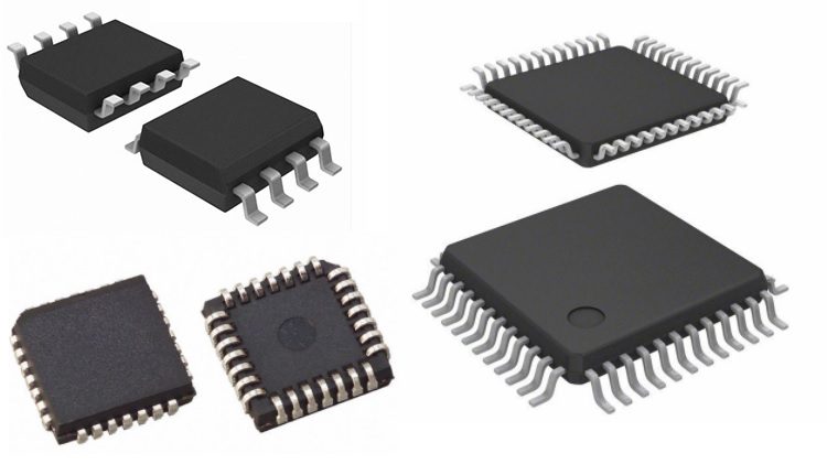
Integrated Circuits (ICs)
An Integrated Circuit or an IC is an integration or incorporation of several electronic components (mainly transistors) on a single device (or chip) made up of a semiconductor material (usually Silicon).
Almost all electronic devices like TVs, Mobile Phones, Laptops, Audio Players, Routers, etc. have Integrated Circuit in them.
ICs are again divided into Analog ICs and Digital ICs. Analog ICs work on Analog Signals like Temperature, Audio, etc. which are continuously varying in nature. Digital ICs on the other hand, work on Discrete Signals i.e. zero volts and a non-zero volts (like 5V or 3.3V) that are represented as Binary 0 and 1.
The commonly used IC in basic electronic circuits are Op – Amps (Operational Amplifiers) like LM741, Timers like NE555, Microcontrollers like AT89S52, Counters like CD4017 and Motor Drivers like L293D.
Vacuum Tubes
Before the invention of transistor vacuum tubes were used in place of transistors. This is defined as an electron tube that controls the flow of electrons in vacuum. CRT screens used in old TVs and computer monitors are best examples for vacuum tubes.
Power sources
DC Power Supply
Bench Power Supply is an important piece of equipment when it comes to working around electronic circuits. Electronic components majorly work on DC Power Supply and hence having a reliable source of DC Power Supply is very important.
There are many types of Power Supplies like AC – to – DC Power Supplies, Linear Regulators, Switching Mode Power Supply, etc.An alternative to bench power supply is to use a wall adapter as per the project requirement like 5V or 12V.
Batteries
Battery is a device that converts chemical energy in to electrical energy and provides power to devices like mobile phones, laptops, flashlights, etc. In electronics, we often use batteries to power our circuits, either to make the circuit portable or just to test the functionality of the circuit.
Batteries come in different sizes and voltage. Batteries are also classified as Primary and Secondary. You can use Primary Batteries until they are drained out and discard them later. In case of Secondary Batteries, you can use them even after they are drained out by recharging them.In electronic circuits, we often use 1.5V AA Batteries or 9V PP3 Batteries.
Display Devices
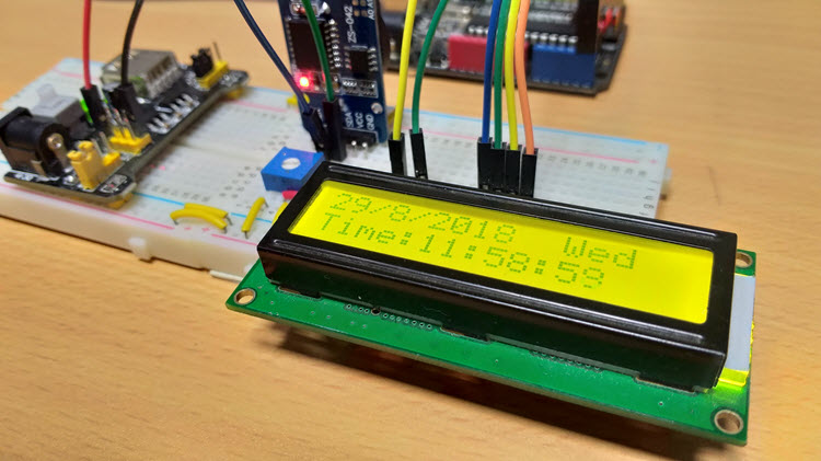
16 x 2 LCD
The most commonly used display module in electronic circuits is an LCD Display and in particular, a 16 x 2 LCD Display. It is an alphanumeric display with two rows and 16 columns and can display a maximum of 32 characters.
7 – Segment Display
Another common display module is the Seven Segment Display. It can be used to display decimal numerals in different electronic devices like clocks, meters, calculators, public information systems, etc.
Passive Components
Passive Components cannot control the flow of current through them i.e. they cannot introduce energy in to the circuit but can increase or decrease voltage and current.
These components don’t depend on the energy source for their operation.Two terminal components like Resistors, Capacitors, Inductors and transformers are examples of Passive Components.
Resistors
The basic of all electronic components are the Resistors. It is a passive electronic components that introduces electrical resistance in to the circuit. Using resistors, we can reduce the current, divide voltages, setup biasing of transistors (or other active elements), etc.
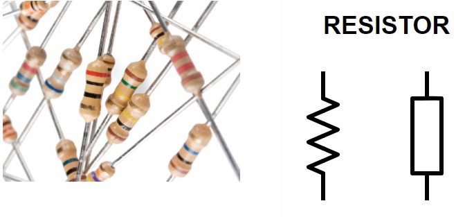
Read about Resistors here: INTRODUCTION TO RESISTORS.
Ohm’s Law defines the behavior of a resistor which states that the current through a conductor is directly proportional to the voltage across the conductor. The proportionality constant is called as Resistance.
The mathematical representation of Ohm’s Law is I = V/R.
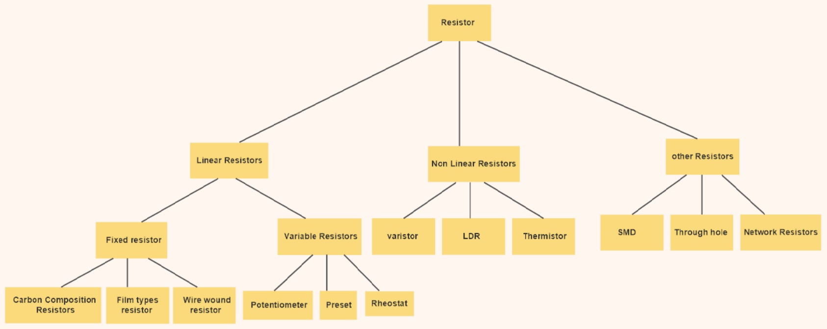
Different types of resistors can be defined according to their function,size,characteristics etc.Resistors are divided in to Fixed Resistors and Variable Resistors.
Fixed Resistors, as the name suggests, have a fixed resistance and its resistance doesn’t change due to external parameters.Variable Resistors, on the other hand, have a variable resistance that can either be changed manually or controlled by external factors like Light Dependent Resistor (LDR) or Thermistor. Below image shows different types of resistors available.
Capacitors
The second important passive components is a capacitor, a device that stores energy in the form of electric field. Most capacitors consists of two conducting plates that are separated by a dielectric material.
If Q is the charge on any one of the conductor plates and V is the voltage between them, then the Capacitance C of the Capacitor is C = Q/V.
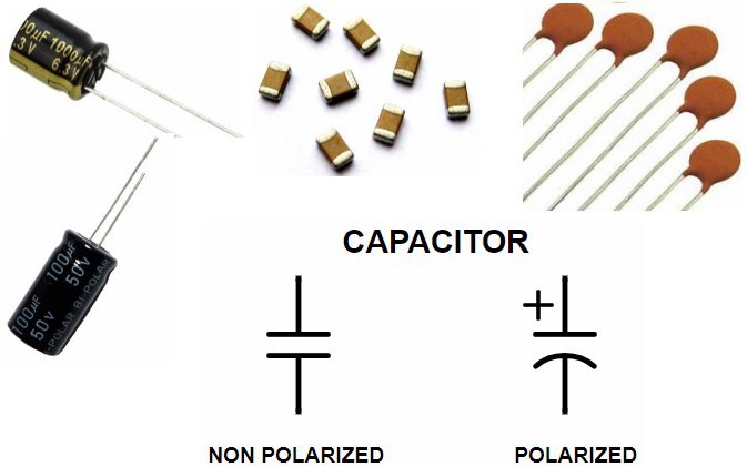
In electronics circuits, a capacitor is mainly used to block DC Current and allow AC Current. The other applications of capacitors are filters, timing circuits, power supplies and energy storing elements.
There are many types of Capacitors like Polarized, Non – Polarized, Ceramic, Film, Electrolytic, Super Capacitors etc.
Also Read INTRODUCTION TO CAPACITORS.
Inductors
If capacitors store energy in the form of electric field, then inductors are devices that store energy in the form of Magnetic Field. Inductor is nothing but a wire that is wound in the form of a coil.
Inductor is widely used in AC equipment like filters, chokes, tuned circuits etc.
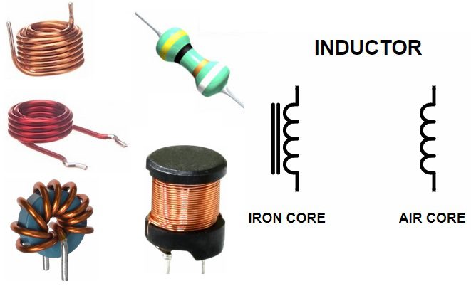
The core around which the coil is wound i.e. air, iron, ferrite etc. will determine the strength of the magnetic field. Inductors opposes the change in electric current through them and the changes in current will result in induction of voltage.
More information on INDUCTORS.
Basic Test and Measurement Equipment
When it comes to designing electronic circuits, testing and measuring various parameters like current, voltage, frequency, resistance, capacitance, etc. is very important. Hence, the Test and Measurement Equipment like Oscilloscopes, Multimeters, Logic Analyzers, Function Generators (or Signal Generators) are often used regularly.
Oscilloscope
The most reliable Test Equipment for observing continuously varying signals is an Oscilloscope. With the help of an Oscilloscope, we can observe the changes in an electrical signal like voltage, over time.
Oscilloscopes are used in a wide range of field like Medical, Electronic, Automobile, Industrial and Telecommunication Applications.
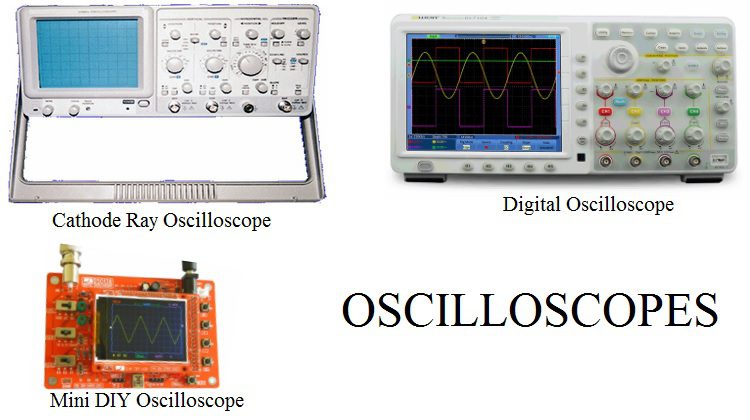
Originally, Oscilloscopes are made up of Cathode Ray Tube (CRT) displays but nowadays, almost all Oscilloscopes are Digital Oscilloscopes with advanced features like storage and memory.
Multimeter
A multimeter is a combination of Voltmeter, Ammeter and Ohmmeter. They provide an easy way to measure different parameters of an electronic circuit like current, voltage etc.
Multimeters can measure values in both AC and DC. Earlies Multimeters are Analog and consists of a pointing needle. Modern Multimeters are Digital and are often called as Digital Multimeters or DMMs.
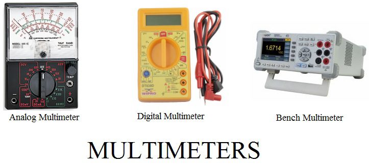
DMMs are available as handheld devices as well as bench devices. A Multimeter can be very handy in finding basic faults in a circuit.
Function Generator or Signal Generator
A Signal Generator, as the name suggests, generates a variety of signals for testing and troubleshooting electronic circuits. The most common types of signals are Triangular Wave, Sine Wave, Square Wave and Sawtooth Wave.
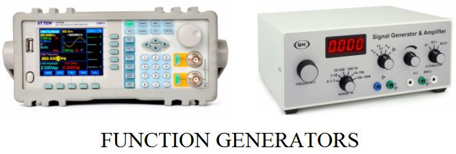
Along with a bench power supply and oscilloscope, a function generator is also an important piece of equipment when designing electronic circuits.
In this article, we have seen few Basic Electronic Components and Test Equipment that we come across very frequently when designing or testing electronic circuits.
There are a lot more components like Transformers, Buttons, Switches, Connectors, etc. which we can explore as we move forward with a project.
The post Basic Electronic Components appeared first on Electronics Hub.
from Electronics Hub https://ift.tt/2PPahhP
Interfacing 128×64 OLED Graphic Display with Arduino – Hook-up Guide & Tutorial
In this project, we will learn about 128×64 Graphics Display, how to interface a 128×64 OLED Graphic Display with Arduino and finally I will display few graphical images and text on this display using Arduino UNO. So, let’s get started.
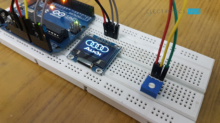
The main limitation of 16×2 LCD displays is that you are constrained to displaying just numbers and alphabets and if you want to display small graphical images, then the struggle begins.
Here comes the 128×64 Graphics OLED Display to the rescue. It is a tiny little display module that can be used to display small graphical images easily using Arduino (or any other microcontroller).
This is a monochrome OLED Display with while light and since it is an OLED display, there is no concept of backlight as individual pixel is self-illuminating. This 128×64 Pixel OLED Display measures about 0.96” diagonally. So, you can understand by this dimension that it is a fairly small display module.
NOTE: I am not sure whether there is any voltage regulator on the board so I have connected it to 3.3V supply (as the OLED Driver/Controller IC is rated for 3.3V). Some boards include a voltage regulator.
Any display module must have an appropriate Driver/Controller Module associated with it. In case of our traditional 16×2 LCD Displays, it is HD44780 IC. Coming to the 128×64 OLED Display module, the Driver module is SSD1306 from Solomon Systech.
This particular driver IC is suitable for driving OLEDs and PLEDs of a resolution of 128×64 Pixels.
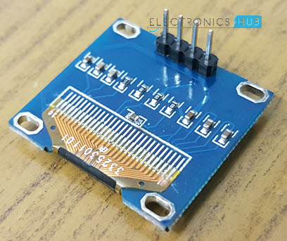
The SSD1306 OLED Driver IC supports various interfaces like Parallel, 4-wire SPI, 3-wire SPI and I2C. This particular OLED Graphic Display which I am using has pins for I2C Communication and interfacing with Microcontrollers.
First thing is the power supply. Find out the power supply requirements of your board and connected to appropriate power supply pin i.e. 5V or 3.3V.
The next important thing is the communication interface. Some modules come with both SPI and I2C Interface pins on board. Check out the pins on your board and proceed with the interface of your choice.
In my case, I have connected the OLED Display Module to 3.3V Supply and as my board has only I2C Communication i.e. SDA and SCL Pins, I have used the same.
Finally, using appropriate libraries with your Arduino IDE. I will talk about the libraries and special tools in the Code section.
Optional Connection: Just to demonstrate the output, I have connected a 10KΩ POT to A0 of Arduino (with its other terminals being connected to 5V and GND).
These libraries are developed by Adafruit and are called Adafruit_SSD1306 and Adafruit_GFX. You can download these libraries from the following links: Adafruit_SSD1306 and Adafruit-GFX-Library.
Download the zip files, extract the contents and place them in libraries folder of Arduino.
The second important thing is that if you want to display any small graphical images, you need to convert them to byte arrays. There are many tools but I have used this online tool.
First, convert your image to a bitmap image (.bmp) file using photoshop or paint. It is important that your image is of the same resolution as you OLED Display i.e. 128×64 in my case.
IMPORTANT NOTE: Before uploading the code, you need to set the resolution of your OLED Display i.e. whether 128×64 or 128×32 by commenting/uncommenting the appropriate value in the Adafruit_SSD1306.h file in the libraries. Do not forget this step.
The post Interfacing 128×64 OLED Graphic Display with Arduino – Hook-up Guide & Tutorial appeared first on Electronics Hub.
from Electronics Hub https://ift.tt/2MHyNDp
Introduction
In almost all the projects that I have implemented so far, I have used the traditional 16×2 Alphanumeric LCD Display to display any vital information from Arduino. It is a great display option if your requirement is to display number and alphabets (and a few special characters as well) in your project.The main limitation of 16×2 LCD displays is that you are constrained to displaying just numbers and alphabets and if you want to display small graphical images, then the struggle begins.
Here comes the 128×64 Graphics OLED Display to the rescue. It is a tiny little display module that can be used to display small graphical images easily using Arduino (or any other microcontroller).
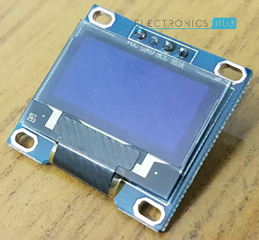
A Brief Note on 0.96 inch 128×64 OLED Graphic Display
Before discussing about the 128×64 Graphical OLED Display Module and interfacing it with Arduino, let me show you the module used in this project. The following image shows a typical 0.96” OLED Graphic Display Module with a resolution of 128×64 Pixels.This is a monochrome OLED Display with while light and since it is an OLED display, there is no concept of backlight as individual pixel is self-illuminating. This 128×64 Pixel OLED Display measures about 0.96” diagonally. So, you can understand by this dimension that it is a fairly small display module.
NOTE: I am not sure whether there is any voltage regulator on the board so I have connected it to 3.3V supply (as the OLED Driver/Controller IC is rated for 3.3V). Some boards include a voltage regulator.
Any display module must have an appropriate Driver/Controller Module associated with it. In case of our traditional 16×2 LCD Displays, it is HD44780 IC. Coming to the 128×64 OLED Display module, the Driver module is SSD1306 from Solomon Systech.
This particular driver IC is suitable for driving OLEDs and PLEDs of a resolution of 128×64 Pixels.
The SSD1306 OLED Driver IC supports various interfaces like Parallel, 4-wire SPI, 3-wire SPI and I2C. This particular OLED Graphic Display which I am using has pins for I2C Communication and interfacing with Microcontrollers.
Interfacing 128×64 OLED Graphic Display with Arduino
Now that we have seen a little bit about the 0.96” OLED Display, let us now proceed with interfacing a 0.96” 128×64 OLED Graphic Display with Arduino. There are two important things to remember before proceeding with the interface.First thing is the power supply. Find out the power supply requirements of your board and connected to appropriate power supply pin i.e. 5V or 3.3V.
The next important thing is the communication interface. Some modules come with both SPI and I2C Interface pins on board. Check out the pins on your board and proceed with the interface of your choice.
In my case, I have connected the OLED Display Module to 3.3V Supply and as my board has only I2C Communication i.e. SDA and SCL Pins, I have used the same.
Finally, using appropriate libraries with your Arduino IDE. I will talk about the libraries and special tools in the Code section.
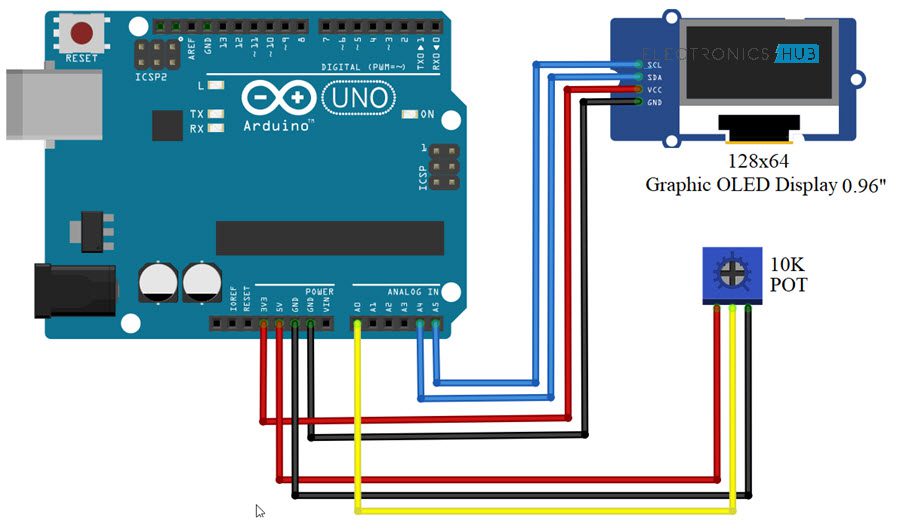
Circuit Diagram
The circuit diagram for interfacing 128×64 OLED Graphic Display with Arduino UNO is shown in the following image.Components Required
- Arduino UNO
- Monochrome 0.96” 128×64 OLED Graphic Display
- Breadboard
- Connecting Wires
- 10KΩ Potentiometer (optional)
Circuit Design
Connect the VCC and GND of the OLED display to 3.3V and GND of Arduino. Then the connect the SDA and SCL pin of the display module to A4 and A5 (Analog Inputs) of Arduino UNO.Optional Connection: Just to demonstrate the output, I have connected a 10KΩ POT to A0 of Arduino (with its other terminals being connected to 5V and GND).
Download Necessary Libraries
Before looking at the code, you need to gather a few things. First thing is the libraries used to drive the OLED Display. You need to download two special libraries: one is for the SSD1306 OLED Driver and the other is for all the Graphics related functions like drawing lines, pixels, circles etc.These libraries are developed by Adafruit and are called Adafruit_SSD1306 and Adafruit_GFX. You can download these libraries from the following links: Adafruit_SSD1306 and Adafruit-GFX-Library.
Download the zip files, extract the contents and place them in libraries folder of Arduino.
The second important thing is that if you want to display any small graphical images, you need to convert them to byte arrays. There are many tools but I have used this online tool.
First, convert your image to a bitmap image (.bmp) file using photoshop or paint. It is important that your image is of the same resolution as you OLED Display i.e. 128×64 in my case.
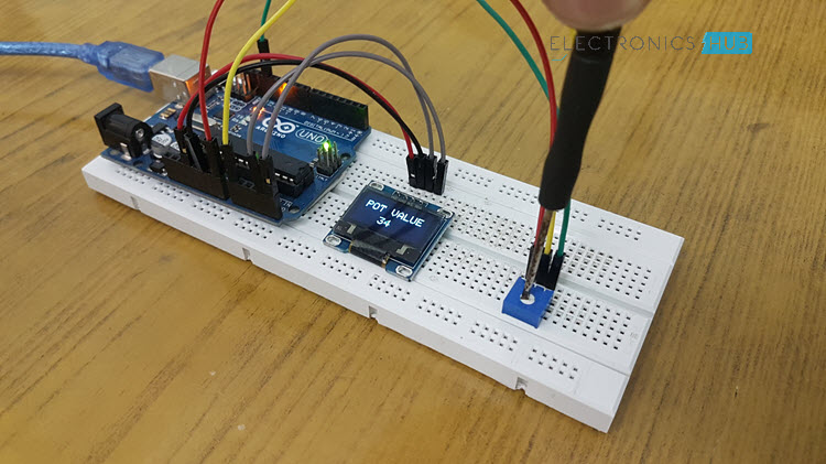
Code
I have used two codes in the project. One code is just for displaying few random graphical images of different logos and the other code is to display the value read from the Potentiometer connected to Arduino. I have included both the codes.IMPORTANT NOTE: Before uploading the code, you need to set the resolution of your OLED Display i.e. whether 128×64 or 128×32 by commenting/uncommenting the appropriate value in the Adafruit_SSD1306.h file in the libraries. Do not forget this step.
Code for Logo
Code for POT Value
The post Interfacing 128×64 OLED Graphic Display with Arduino – Hook-up Guide & Tutorial appeared first on Electronics Hub.
from Electronics Hub https://ift.tt/2MHyNDp
Thursday, 30 August 2018
IOT Prison Break Monitoring & Alerting System
Download Project Document/Synopsis Well it is a quite shocking fact but prison escapes are not very uncommon occurrences. There is no exact data count but we have all heard and still keep hearing of a variety of prison escapes happening globally. The fact that such number of inmates may still be roaming among us is […]
from NevonProjects https://ift.tt/2Nzxyme
from NevonProjects https://ift.tt/2Nzxyme
Introduction to Sinusoidal Signal Processing with Scilab
This article discusses basic signal-processing tasks that can be performed using a free and open source alternative to MATLAB.
from All About Circuits Technical Articles https://ift.tt/2MG3NUw
from All About Circuits Technical Articles https://ift.tt/2MG3NUw
The Dawn of Gallium Oxide? Researchers Announce New Transistor to Boost Electric Vehicle Batteries
Researchers from the University at Buffalo have announced a gallium oxide transistor with EV batteries in their sights.
from All About Circuits News https://ift.tt/2C2J9cb
from All About Circuits News https://ift.tt/2C2J9cb
Optronic Sensors for Imaging (Part 2 of 6)
 Imaging sensors are an important component of a wide range of defence systems and are projected to play a growing role in the coming years. This article discusses CCD, CMOS and Ladar sensors in detail. Two most common types of imaging sensors with potential military applications include charge-coupled device (CCD) sensors and complementary metal-oxide semiconductor […]
The post Optronic Sensors for Imaging (Part 2 of 6) appeared first on Electronics For You.
from Electronics For You https://ift.tt/2BZDcgg
Wednesday, 29 August 2018
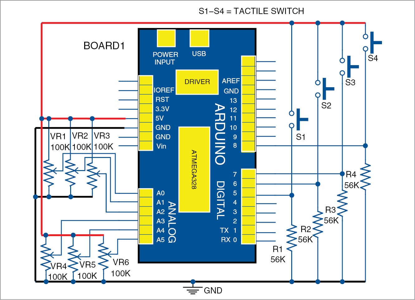
Clap Switch Circuit for Devices using 555 and 4017
We have already seen the circuit diagram, working and applications of 9 way Clap Switch Circuit. Now, we are going to deal another circuit named clap switch circuit for devices. I will present two circuits for clap switches, both of these circuits will be based on 555 IC and 4017 IC.
Using these circuits, you can control electrical appliances by simple clapping. Summary of the project given below:
Clap Switch Circuit Summary
- If you wish to “ON” and “OFF” the device without moving from your place, then this circuit is helpful for you.
- One more plus point of this circuit is that there is no fear of the electrical shocks as you are not required to touch any of the mechanical switches physically.
- Visual indication of the devices is also provided to you.
- With the help of this circuit, speed of the fan can also be controlled by connecting regulator with individual outputs.
Clap Switch Circuit using 555 and 4017
In the first circuit, I will control a single relay using clap switch. When you clap once, the relay is activated and the light (or any load) is turned ON. When you clap for the second time, the relay is deactivated and the light is turned OFF.
Circuit Diagram
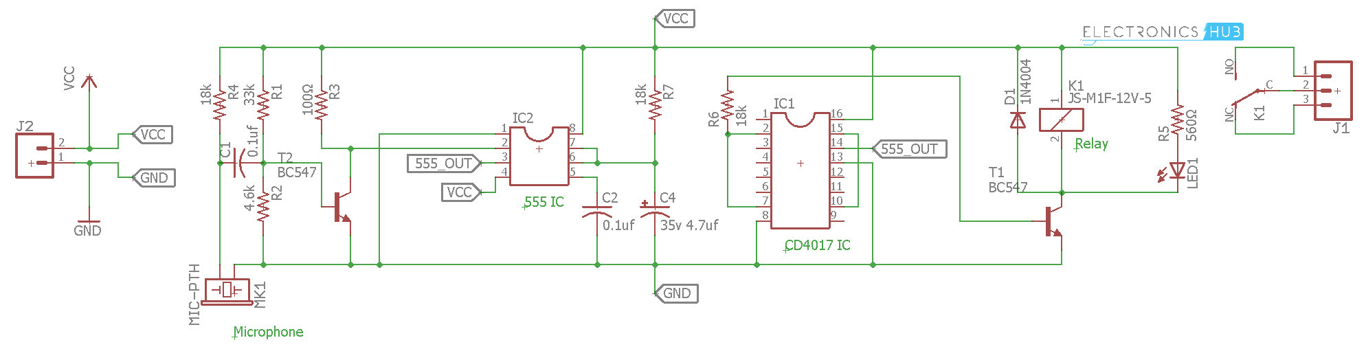
Components Required
- 555 IC
- CD4017 IC
- Relay
- Resistors – 100Ω, 560Ω, 4.6KΩ, 18KΩ x 3, 33KΩ
- Capacitors – 0.1µF x 2, 4.7µF
- Microphone
- BC547
- 1N4004 Diode
- LED
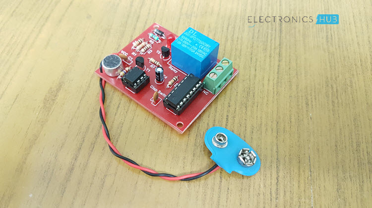
PCB for Clap Switch Circuit
I have made a simple PCB for the above mentioned clap switch circuit. The PCB layout is shown on the following image.
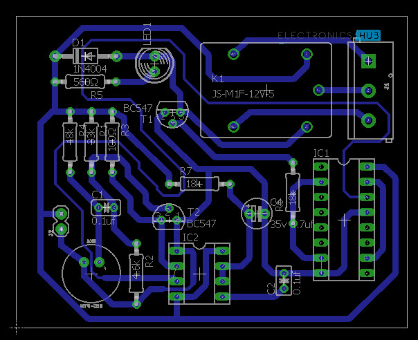
If you want to make your own PCB, I have included the Eagle CAD PCB Files. You can download them from here.
Clap Switch Circuit for Multiple Devices
In the second circuit (similar to the one above), I have added a few extra relays to control additional devices.
Circuit Diagram
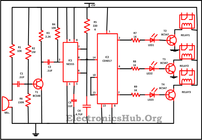
Circuit Diagram of Clap Switch – ElectronicsHub.Org
Circuit Components
- IC
- IC1(NE555) – 1
- IC2(CD4017) – 1
- Resistor
- R1,R4(10K) – 2
- R2,R7,R8,R9(1K) – 4
- R3(2.2K) – 1
- R5(220E) – 1
- R6(150) – 1
- C1,C2(.1uf) – 2
- C3(1uf) – 1
- C4(4.7uf) – 1
- Mic – 1
- LED – 3
- T1(BC548) – 1
- T2,T3,T4(BC547) – 3
- Relay – 3
Clap Switch Circuit Description
Along with some of the other components, this circuit is mainly based on the two ICs i.e. NE555 timer along with CD4017.
IC 555 timer in this circuit is wired like a monostable oscillator. For this circuit, IC NE555 monostable produces a clock pulse, which is used to give an oscillating wave at IC1 pin 3 which is an output pin. Monostable (or you can say one shot multivibrator) contains only one steady state and all we need is to trigger it externally to return it in reverse direction to its original state.
Another one is the CD4017 which is a CMOS counter/divider IC. It receives a clock signal through the clock input and in the sequential manner it turns ON all the 10 outputs, every time it gets the clock input pulse.
In order to get familiar with the working of the IC, it is essential for the one to get familiar with the every pin of the IC. These IC consist of 3 input pins along with 10 output pins also have one pin for ground and one more for the power supply and one more pin for the Carry out. Pin diagram of the IC is designed below –
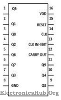
- Input Pin:
- Reset Pin (Pin 15) – The counter is reset to the zero position by this pin. Suppose you wish that the counter will only count till third position then you need linked the fourth pin with 15 pin. So after reaching to the third output it will automatically begin its counting from zero.
- Clock Pin (Pin14) – In each of the timing pin 14 moves at high the output will be given to you. From the initial clock pulse output will be received at the pin 3 likewise for the next clock pulse output will be received at the pin 2 and so on.
- Clock Inhibit Pin (Pin 13) – The counter is switched to “on” and “off” by this pin. If you need that the counter to be switched off then for that pin 13 must be at high state. If the pin is at high then it will disregard the clock pulse without paying attention that how much time you press the switch i.e. the count will not go forward. Pin 13 in our circuit is grounded.
- Output Pin (Pin Q0- Q9) -It is used to get the input in chronological order. Like pin 3 will give you the output for the first pulse and so on.
- Ground Pin (Pin 8) and Supply pin (pin 16) – For the proper working of these IC these pins are used to give ground as well as power supply.
- Carry out Pin (Pin 12) – These pins are used to link one or more CD4017 IC with each other. Suppose you have a desire to connect one more CD4017 IC then attach pin 12 to the clock input to its next one. The carry pin of first CD4017 is connected to clock input of the second and the carry pin of the second is connected to the clock input of the third and so on. In our circuit we left this pin as we have desire of only one IC in our circuit.
How Clap Switch Circuit Works?
At the time when some one slap in front of the Mic the sound signal is converted into the electrical signal by the condenser microphone.These signals are then given to the transistor T1 base which in return trigger the IC1 pin2. And with the help of the formula shown below the time period for which the output stay in the high position can be calculated –
T = 1.1*R5*C4
At the moment the output from the IC1 pin 3 is given to CD4017 decade counter 14 pin, which supply a clock pulse for the proper working of IC2. The counting of the CD4017 begins from the zero after getting the clock input. And it moves to forward one by one at each time whenever pin 14 moves to high (as in front of the mic we clap). Like we get output from the pin 2 for the first clap i.e. Q1 and LED1 will shine and the device connected to relay start operating . While for the second clap output will receive at pin 4 and LED2 will shine while at this time LED1 turn off and so on. At each output point you need to attach the individual relay .10 individual devices can be controlled with the help of this circuit just connect the relay at appropriate outputs of CD4017.
Note: For some more interesting projects and circuit diagrams, visit Mini Projects on Electronics.
The post Clap Switch Circuit for Devices using 555 and 4017 appeared first on Electronics Hub.
from Electronics Hub https://ift.tt/2NxxzHt
PCB Design: How to Choose a PCB Manufacturer
In this article, we will discuss some best practices for how to choose a manufacturer to produce your custom PCB board.
from All About Circuits Technical Articles https://ift.tt/2wwL9Ud
from All About Circuits Technical Articles https://ift.tt/2wwL9Ud
Meet WARLORD: Metawave Aims to Bring Millimeter-Wave RADAR Sensors to the Automotive Industry
We've heard all about LiDAR sensors for autonomous vehicle applications. But what about RADAR?
from All About Circuits News https://ift.tt/2Nr7QQK
from All About Circuits News https://ift.tt/2Nr7QQK
Graphical Data Display with Arduino and HTML5
 Most Arduino-based projects use LCDs to show data, but this project instead uses webpage so that more details can be displayed in a graphical form and accessed from anywhere through the Internet. The project takes variable analogue inputs from Arduino and displays results in graphical form on a webpage that supports HTML5. The project presented […]
The post Graphical Data Display with Arduino and HTML5 appeared first on Electronics For You.
from Electronics For You https://ift.tt/2POm2Vt
Arduino DS3231 RTC Module Tutorial
In this project, I will discuss about DS3231 RTC Module, important components and features of this module and finally show you how to Interface a DS3231 Real Time Clock (RTC) Module with Arduino.
Introduction
Real Time Clock or RTC is a timekeeping device in the form of an Integrated Circuit or IC. RTC is an integral component of many time critical applications and devices like Servers, GPS, Data Loggers etc.
I have already implemented a couple of projects using Real Time Clock or RTC Module earlier with both 8051 Microcontroller and Arduino.
With 8051, I have used DS1307 RTC Module in a project called RFID BASED CAR PARKING SYSTEM. Coming to Arduino, I have used the same DS1307 RTC in ARDUINO ALARM CLOCK and ARDUINO REAL TIME CLOCK TUTORIAL USING DS1307. If you want a quick reference, you can go through the provided links.
Also, in the Arduino Real Time Clock Tutorial using DS1307 project, I have talked about the need for an RTC. So, I won’t go into that aspect again. I will directly jump into the IC of interest: the DS3231 RTC IC.
A Brief Note on DS3231 RTC IC
The DS3231 is an RTC IC developed by Maxim Integrated. It is a low cost, extremely accurate RTC IC with communication over I2C Interface. An interesting feature of DS3231 RTC IC is that it has integrated crystal oscillator and temperature sensor and hence you don’t have to connect an external crystal.
It is available in SO-16 Package. Although it need only 8 pins in the available 16 pins to function, the integration of crystal makes the IC Bulkier and hence it is packed as a 16-pin IC instead of 8-pin IC.
The following image shows the Pin diagram of the DS3231 RTC IC.
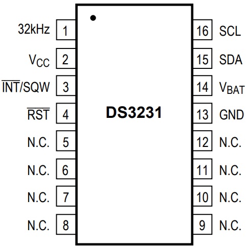
Pin Description of DS3231 IC
Coming to the pin description of DS3231 IC, the following table gives a simple functionality overview of the pins.
|
Pin Number |
Pin Name |
Description |
|
1 |
32KHz |
32KHz output |
| 2 | VCC |
DC Power Pin |
|
3 |
INT/SQW | Active LOW Interrupt or Square wave output |
| 4 | RST |
Active LOW Reset |
|
5 – 12 |
NC | No Connection |
|
13 |
GND |
Ground |
| 14 | VBAT |
Back-up Power Supply Input from Battery |
|
15 |
SDA |
Serial Data I/O |
|
16 |
SCL |
Serial Clock Input |
NOTE: Pins 5-12 are NC Pins. They can be tied to GND.
DS3231 RTC Module
Using DS3231 IC as the main component, several manufacturers developed DS3231 RTC Modules with all the necessary components. Almost all the modules available today consists of an additional IC, 24C32N (or something similar). This secondary IC is an EEPROM IC of 32Kb size.
Since both RTC and EEPROM ICs are interfaced through I2C Protocol, you won’t need any extra pins as both these I2C Devices can act as slaves while a microcontroller acts as a master.
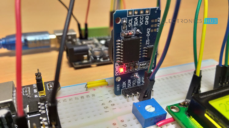
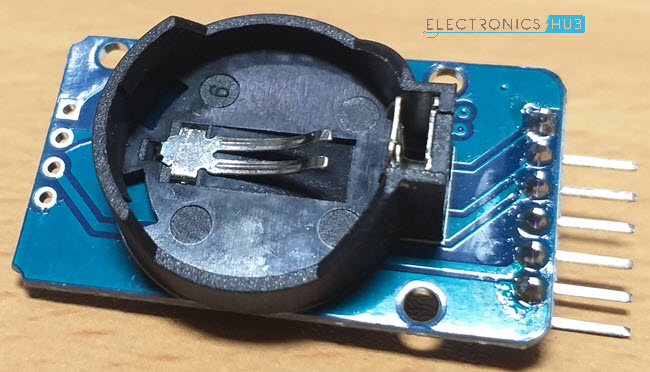
The DS3231 RTC Module used in this project is shown in the image below.
Since RTC is all about maintaining time irrespective of the power supply, you can connect a 3V CR2032 Lithium Battery to the RTC IC to keep the clock ticking. In the DS3231 Module, there is a provision for you to connect a battery using the battery holder provided on the back.
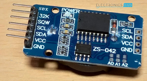
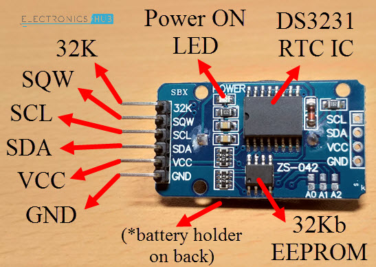
Components and Pin of DS3231 RTC Module
As mentioned earlier, DS3231 IC and 24C32 EEPROM IC are the main components on a typical DS3231 RTC Module board. Apart from that, there are a few other components like Power ON LED, few resistors, capacitors, a battery holder and pins for connecting with microcontroller.
The following image shows the components and pins on the DS3231 RTC Module.
Interfacing DS3231 RTC Module with Arduino
If you remember an earlier project using MicroSD Card Adapter, I have setup a simple data logging application where the data from a sensor is captured and stored in the microSD Card in the form of a text file.
By integrating a Real Time Clock like DS3231 to the above project, you can keep track of the data log with accurate time details.
Hence, interfacing DS3231 RTC Module with Arduino has a numerous application and advantages.
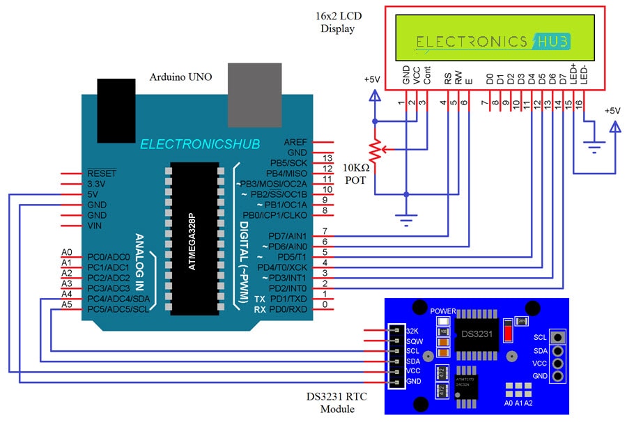
Circuit Diagram
Components Required
- Arduino UNO
- DS3231 RTC Module
- 16×2 LCD Display
- Mini Breadboard
- 10KΩ POT
- Connecting Wires
Circuit Design
First, let me begin the connections between Arduino and DS3231. Since the interface between them is I2C, identify the I2C Pins on your Arduino Board (if you are using any other board than UNO).
In Arduino UNO, A4 and A5 are SDA and SCL pins. Connect these pins with corresponding SDA and SCL pins of the DS3231 Module. Also, connect the VCC and GND of the RTC Module to +5V and GND of Arduino.
To view the output, I have used an LCD Module. Connect the RS and E pins of LCD to Pins 7 and 6. Connect D4-D7 of LCD to 5-2 of Arduino.
Code
I have used a special library called “RTClib” from Adafruit (which is a forked version of JeeLab’s RTC Library). Download the library from this link and place the extracted folder in the libraries directory of Arduino.
Since the communication is I2C, I have also used the “Wire” library. You don’t need to download this library as it is integrated with Arduino IDE.
Working
The working of the Arduino DS3231 RTC Module Interface is very easy. Arduino first initializes the RTC Module with its slave address (0x68 for DS3231 IC).
Arduino then updates the internal registers of the RTC IC with the date and time at which the code is compiled and uploaded to Arduino. The uploaded date and time can be viewed on the LCD display.
If you want the DS3231 Module to keep time even after you disconnect power to Arduino, you can connect a 3V Lithium Battery.
Applications
- Servers
- Data Loggers
- GPS Modules
- Power Meters
The post Arduino DS3231 RTC Module Tutorial appeared first on Electronics Hub.
from Electronics Hub https://ift.tt/2PMWEPW
Basic Electrical Circuits-Components,Types
What is an Electric Circuit?
An Electric Circuit is a closed path for transmitting an electric current through the medium of electrical and magnetic fields. The flow of electrons across the loop constitutes the electric current. Electrons enter the circuit through the ‘Source’ which can be a battery or a generator. The source provides energy to the electrons, by setting up an electrical field which provides the electromotive force.
The electrons leave the circuit through the load, to the earth ground, thus completing a closed path. The load or output can be any simple home appliance like television, lamp, refrigerator, or can be a complex load such as that on a hydroelectric power generating station.
A simple electric circuit consists of a source (such as a battery), wires as conducting medium and a load (such as a light bulb). The battery provides required energy for flow of electrons, to the light bulb.
Basic Circuit Elements
As mentioned above in the introduction, a circuit is an interconnection of elements. These elements are classified into active or passive elements, based on their capability to generate energy.
Active Circuit Elements
Active Elements are those which can generate energy. Examples include batteries, generators, operational amplifiers and diodes. Note that in an electrical circuit, the source elements are the most significant active elements.
An energy source, whether a voltage or current source, is of 2 types – Independent and Dependent sources. Example of an Independent source is the battery which provides a constant voltage to the circuit, irrespective of the current flowing through the terminals.
Example of a dependent source is a transistor, which provides current to the circuit, depending upon the voltage applied to it. Another example is an Operational Amplifier, which provides voltage, depending upon the differential input voltage applied to its terminals.
Passive circuit Elements
Passive Elements can be defined as elements which can control the flow of electrons through them.They either increase or decrease the voltage. Here are some examples of passive elements.
Resistor: A resistor opposes the flow of current through it. For a linear circuit, Ohm’s law is applicable, which states that voltage across the resistor is directly proportional to the current flowing through it, the proportional constant being the resistance.
Inductor: An inductor stores energy in form of the electromagnetic field. The voltage across an inductor is proportional to the rate of change of current flowing through it.
Capacitor: A capacitor stores energy in form of the electrostatic field. The voltage across a capacitor is proportional to the charge.
Types of Electrical Circuits
DC Circuits
In DC Circuits, the excitation applied is a constant source. Based on the type of connection of active and passive components with the source, a circuit can be classified into Series and Parallel circuits.
Series Circuits
When several passive elements are connected in series with an energy source, such a circuit is known as a series circuit. For a series circuit, same amount of current flows through each element and voltage is divided. In series circuit, as the elements are connected in a line,if there is faulty element among them ,complete circuit acts as open circuit.
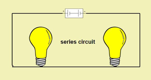
- For a resistor connected in DC circuits, the voltage across its terminals is directly proportional to the current passing through it, thus maintaining a linear relationship between the voltage and current. For resistors connected in series, the total resistance is equal to the sum of all resistance values.
- For capacitors connected in series, the total capacitance is equal to the sum of reciprocals of all capacitance values.
- For inductors connected in series, total inductance is equal to the sum of all inductance values.
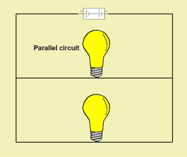
Parallel Circuits
In a parallel circuit, one terminal of all the elements is connected to the one terminal of the source and the other terminal of all elements is connected to the other terminal of the source.
In parallel circuits, the voltage remains the same in the parallel elements while the current changes. If there is any faulty element among parallel elements there is no effect on the circuit.
- For resistors connected in parallel, the total resistance is equal to the sum of reciprocals of all resistance values.
- For capacitors connected in series, the total capacitance is equal to the sum of all capacitance values.
- For inductors connected in series, total inductance is equal to the sum of all reciprocals of inductance values.
AC circuits
Ac circuits are those circuits, Whose excitation element is an AC source. Unlike DC source which is constant AC source has variable current and voltage at regular intervals of time. Generally, for high power applications, AC circuits are used.
Simple AC Circuit using resistance
For alternating current passing through the resistor, the ratio of current and voltage depends upon the phase and frequency of the supply. The applied voltage will change constantly with time and Ohm’s law can be used to calculate current passing through the resistor at any instant of time.
In other words, if at time t seconds, the value of voltage is v volts, current will be:
i = v/R
where the value of R is always constant.
Above equation shows that polarity of current depends upon that of the voltage. Also, both current and voltage reach their maximum and zero points at the same time. Thus, for a resistor, voltage is in phase with the applied current.
Consider the below circuit diagram
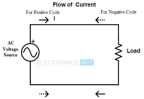
When the switch is closed, current passes through the resistor and is given by the below equation
i=Im cos(ωt+Φ)
Voltage,V=IR=RIm cos(ωt+Φ)
For a resistor, both voltage and current values will rise and fall at the same time. Hence, the phase difference between voltage and current is zero.
AC Circuit using pure inductance
A coil of thin wire wrapped on a cylindrical core is known as an Inductor. The core can be an air core (hollow laminated) or an iron core. As alternating current flows through the inductor, the magnetic field also changes. This change in magnetic field results in an induced voltage across the inductor. As per Lenz law, the induced voltage is such that it opposes the flow of current through it.
During the first half cycle of the source voltage, the inductor stores energy in form of magnetic field and in the next half, it releases energy.
The induced EMF is given as below
e=Ldi/dt
Here, L is the self-inductance.
Now, Input AC voltage applied is given as v(t)=Vm Sinωt
Current through the inductor is:I(t)=Im Sinωt
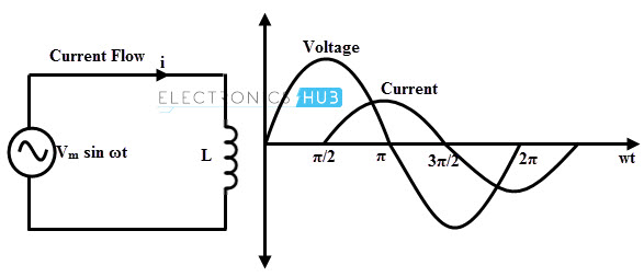
So, the voltage across the inductor would be
e=L di/dt=wLI_m coswt=wLI_m sin(wt+90)
Thus, for an inductor, voltage leads the current by 90 degrees.
Now, resistance by an inductor is termed as Reactance and given by
Thus, impedance or resistance is proportional to rate of change of current for an inductor.
AC Circuit with a capacitor
For a constant DC supply, the capacitor plates charge up to the applied voltage, stores this charge temporarily and then starts discharging. Once a capacitor is fully charged, it blocks the flow of current as the plates get saturated.
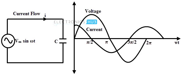
When AC supply voltage is applied to a capacitor, the rate of charging and discharging depends upon the supply frequency. Voltage across the capacitor lags the current flowing through it by 90 degrees.
Current through the capacitor is given as
e = Ldi/dt
The capacitive reactance is given as:
e = Ld/idt
Thus, impedance or reactance to AC supply is inversely proportional to the frequency of supply.
What is a short circuit and an open circuit?
Short Circuit
A low or negligible resistance connection between two conductors in an electric circuit is termed as a short circuit. A short circuit would result in the production of more heat and eventually resulting in sparks, flames or smoke.
A short circuit can be caused due to loose connections, faulty insulation, abrupt chewing up of wires by pests, and old appliances. One of the best and commonly used techniques to prevent damages using short circuit is using a fuse or a circuit breaker.
Open Circuit
An open circuit is caused due to an interruption in the electrical circuit. When any element in a circuit is left unconnected, an open circuit is created. While voltage across an open circuit has some finite value, current is zero.
Circuit Protection
Deliberate installation of a weak link within an electrical circuit is known as circuit protection. Purpose behind this installation is the prevention of damage due to short circuit, excess amount of temperature and other damages.
A circuit protection device can be a fuse, circuit breaker, a thyristor or a switch.
The post Basic Electrical Circuits-Components,Types appeared first on Electronics Hub.
from Electronics Hub https://ift.tt/2wwBn4f
Tuesday, 28 August 2018
Guide to PCB Design: How to Generate Manufacturing Files for Custom Printed Circuit Boards
In this article, we'll go over the basics of generating manufacturing files for PCB design and manufacturing.
from All About Circuits Technical Articles https://ift.tt/2oghESy
from All About Circuits Technical Articles https://ift.tt/2oghESy
Guide to PCB Design: From PCB Schematic to Board Layout
In this article, you will learn the basics of how to plan a schematic for a custom PCB and lay out your PCB prototype design.
from All About Circuits Technical Articles https://ift.tt/2PM7BRW
from All About Circuits Technical Articles https://ift.tt/2PM7BRW
Tutorial: Electrical Power and Watts
 In this video, the presenter will be giving a short tutorial on electrical power and watts. A practical example of light bulb power measurement is shown as well as a demo of how to calculate appropriate resistor sizes. Courtesy: Afrotechmods
The post Tutorial: Electrical Power and Watts appeared first on Electronics For You.
from Electronics For You https://ift.tt/2NqMbbx
Home Automation using Bluetooth of ESP32
 In this project, we will be dealing with the inbuilt Bluetooth feature in ESP32 Development board and try to build an application around it. The Bluetooth system can be divided into two different categories: Classic Bluetooth and Bluetooth Low Energy (BLE). ESP32 supports dual-mode Bluetooth, meaning that both Classic Bluetooth and BLE are supported by […]
The post Home Automation using Bluetooth of ESP32 appeared first on Electronics For You.
from Electronics For You https://ift.tt/2ojZRdb
Monday, 27 August 2018
How Cloud-Based CAE Is Changing Prototyping: An Interview with Ian Campbell, CEO of OnScale
The days of manual prototyping may be numbered, but so could prohibitively expensive IP licenses.
from All About Circuits News https://ift.tt/2Nlcujm
from All About Circuits News https://ift.tt/2Nlcujm
Exploring the AIoT Revolution!
 Take off with TAITRONICS and AIoT Taiwan in this October! TAITRONICS, the“must-visit” professional trade shows for unlimited opportunities in Electronics! As it enters its 44th edition, TAITRONICS is successfully leading Taiwan’s electronics industry through a new paradigm shift. The global electronics industry is now moving from simple mass production, technology-oriented development mode to multi-integrations of […]
The post Exploring the AIoT Revolution! appeared first on Electronics For You.
from Electronics For You https://ift.tt/2LtJ2pD
OpenSCAD Software for 3D Modelling
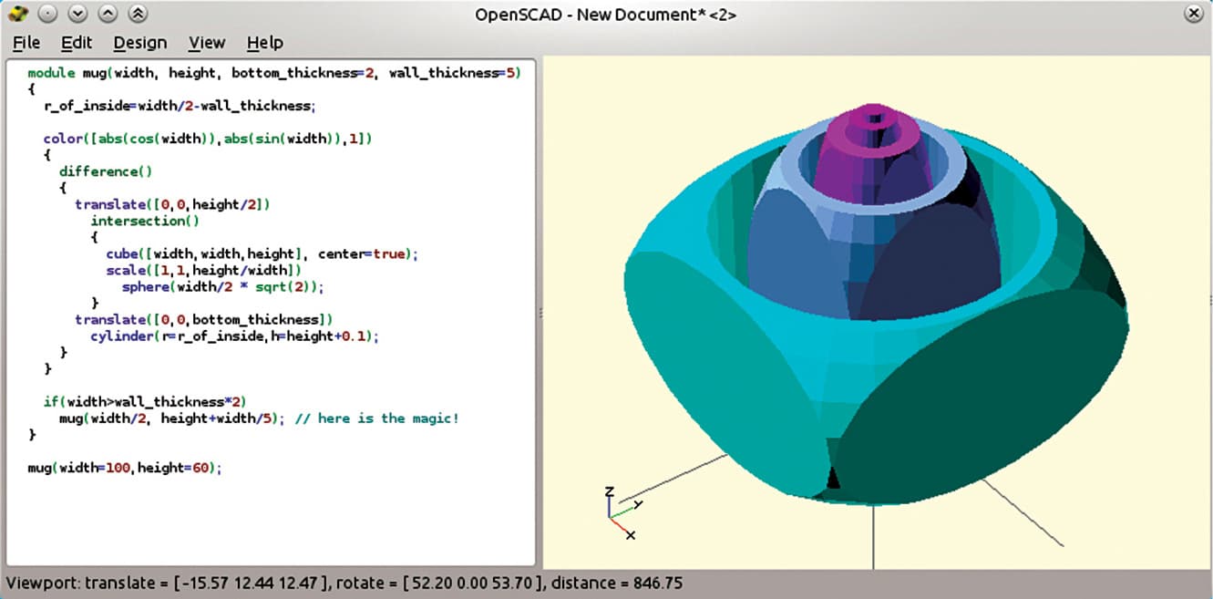 Designing prototypes is made easier by creating the model digitally first. This ensures accuracy and flawlessness in the design before moving ahead with the physical creation. For this purpose, computer-aided design (CAD) software becomes highly beneficial. OpenSCAD is a great option in this category. It supports 3D solid-modelling, which provides an extra sense of accuracy […]
The post OpenSCAD Software for 3D Modelling appeared first on Electronics For You.
from Electronics For You https://ift.tt/2MYLkl8
IOT Energy Meter with Current, Voltage and Cost Monitoring System
Observing and monitoring your power utilization for verification is a not a easy task today since regularly checking the meter room is very tedious task Well, it is very important to know whether you are charged likewise so the need is very sure. Well, we have made a system that allows users to monitor energy […]
from NevonProjects https://ift.tt/2LvDyue
from NevonProjects https://ift.tt/2LvDyue
Sunday, 26 August 2018
Accident Avoiding System with Crash Detection and GPS Notification
When an individual riding his/her Vehicle, meets with a mishap, quite possibly the individual may experience the ill effects of genuine damage or lapse immediately and there is nobody around to help him. Well, this project is an answer to the issue. The system acts as an accident avoidance and detection system that gathers all […]
from NevonProjects https://ift.tt/2Nm6NS0
from NevonProjects https://ift.tt/2Nm6NS0
Multicontroller based Wheelchair Safety using Android, Touch, Speech & Gesture Control
Locomotion is one the basic needs of humans which is lacked by people having limited abilities which render them to use wheelchair for moving from one place to another. The purpose of this project is to serve these people by automating the process of moving in any direction using Different methods over Raspberry Pi. This […]
from NevonProjects https://ift.tt/2PGuXrV
from NevonProjects https://ift.tt/2PGuXrV
Saturday, 25 August 2018
High-Voltage Generator for Microcontroller Projects
 To drive small devices like neon lamps, you need a high-voltage DC power supply. This circuit is a simple DC-to-DC boost (step-up) converter for general-purpose applications. It uses readily available parts that can be bought from any electronic components store. The author’s prototype is shown in Fig. 1. Circuit and working The circuit diagram of […]
The post High-Voltage Generator for Microcontroller Projects appeared first on Electronics For You.
from Electronics For You https://ift.tt/2NeSvCU
Friday, 24 August 2018
FPGA Design Software: An Overview of Time-to-Integration Features in Xilinx’s Vivado Design Suite
This article will look at some of the most important features of the Xilinx Vivado Design Suite which accelerates the "time to integration" of the design procedure.
from All About Circuits News https://ift.tt/2wrrOU6
from All About Circuits News https://ift.tt/2wrrOU6
QLED and IGZO: The Future of Television Display Technology
 Product display screens are output devices that are used to represent output data or information. These are used in almost all electronic devices, such as mobile phones, televisions, refrigerators and computers. A few years ago, cathode ray tubes (CRTs) were used as displays in televisions. Researchers explored this field and, with the help of different […]
The post QLED and IGZO: The Future of Television Display Technology appeared first on Electronics For You.
from Electronics For You https://ift.tt/2P2O12K
Thursday, 23 August 2018
World’s Smallest Single-Atom Transistor Functions at Room Temperature, Sans Semiconductor
Researchers from the Karlsruhe Institute of Technology in Germany have announced a working single-atom transistor that operates at room temperature without a semiconductor present.
from All About Circuits News https://ift.tt/2w2XMH5
from All About Circuits News https://ift.tt/2w2XMH5
Newest World’s Smallest Single-Atom Transistor Functions at Room Temperature, Sans Semiconductor
Researchers from the Karlsruhe Institute of Technology in Germany have announced a working single-atom transistor that operates at room temperature without a semiconductor present.
from All About Circuits News https://ift.tt/2w2XMH5
from All About Circuits News https://ift.tt/2w2XMH5
The Convergence of Automotive Trends: A Conversation with GaN Systems CEO Jim Withers
The automotive landscape is changing rapidly. GaN Systems CEO Jim Witham spoke with AAC about the unique challenges of efficient power in automotive applications and how autonomous vehicles represent a convergence of trends across the industry.
from All About Circuits News https://ift.tt/2BGf4Pm
from All About Circuits News https://ift.tt/2BGf4Pm
Raspberry Pi Air and Noise Pollution Monitoring System Over IOT
In recent day scenario, the non-stop increase in air and sound pollution prove to be an big alarming problem. It has become mandatory to control and appropriately monitor the situation so that the required steps to control the situation can be undertaken. In this project, an IOT-based method using RasberryPi is used to monitor and […]
from NevonProjects https://ift.tt/2PvwdOB
from NevonProjects https://ift.tt/2PvwdOB
Peizo Based Visitor Sensing Welcome Mat
Download Project Document/Synopsis How smart is your doormat? Is it just a simple carpet used only for wiping feet before coming inside? Doormat should do a lot more than that. So here we have made an project which notifies you when any guest or visitor steps at doormat. For this purpose we here use piezoelectric […]
from NevonProjects https://ift.tt/2wjr5V3
from NevonProjects https://ift.tt/2wjr5V3
Smart Portable Cell Phone Jammer Project
Download Project Document/Synopsis Several years have seen a dramatic boom in the radio communications sector, hence, raising the amount of consumers of mobile communication apparatus. This underscores the need for a more efficient and more dependable signal jammer. In tight security places, it is mandatory for individuals to turn off their phones. Likewise, in examination […]
from NevonProjects https://ift.tt/2Pvwa5n
from NevonProjects https://ift.tt/2Pvwa5n
Power Efficient Mini Inverter Project
Download Project Document/Synopsis Inverters are widely used in the domestic as well as industrial environments to serve as second line of source in case of power cut form the electricity utility grids. Inverter is the device that powers the electric appliances in the event of the power failure. Inverter as the name implies first converts […]
from NevonProjects https://ift.tt/2whkqe4
from NevonProjects https://ift.tt/2whkqe4
Fire Detection and Alarm Mini Project
Download Project Document/Synopsis No smoking zones are meant to ensure smoke free areas which promote good health and well being. Especially in public places no smoking zones ensure smoke free environment for people and children. But it is not feasible to manually monitor these zones to ensure a smoke free environment and an automated system […]
from NevonProjects https://ift.tt/2PvoC2C
from NevonProjects https://ift.tt/2PvoC2C
Automated Smoking Zone Monitoring & Alerting Project
Download Project Document/Synopsis No smoking zones are meant to ensure smoke free areas which promote good health and well being. Especially in public places no smoking zones ensure smoke free environment for people and children. But it is not feasible to manually monitor these zones to ensure a smoke free environment and an automated system […]
from NevonProjects https://ift.tt/2wj859m
from NevonProjects https://ift.tt/2wj859m
GSRTC Smart Card
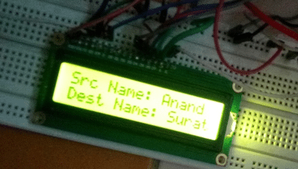 This project is based on the AEIOU heuristic framework of Design Engineering Approach. Design for Performance, Safety and Reliability is ensured in terms of fast response, restricted entry and authentic user. Design for Ergonomics and Aesthetics is ensured in terms of hassle free (no currency change) and a smart card that the user can carry […]
The post GSRTC Smart Card appeared first on Electronics For You.
from Electronics For You https://ift.tt/2o4II7o
Arduino MCP2515 CAN Bus Interface Tutorial
In this project, we will learn about the MCP2515 CAN Controller Module, how to interface the MCP2515 CAN Bus Controller with Arduino and finally how to enable communication between two Arduino board with the help of two MCP2515 CAN Controllers and the CAN Protocol.
Introduction
Controlled Area Network of simple CAN is a bus standard that allows a Microcontroller and its peripheral devices to communicate without the need of a host device or a computer.
Developed by Robert Bosch GmbH, CAN is protocol is main used in automobiles for communication between a control unit and its components.
For example, the Engine Control Unit is a major control using in a car. This unit is connected to many sensors and actuators like air flow, pressure, temperature, valve control, motors for air control etc. The communication between these modules and the control unit is through CAN Bus.
In order to understand a little bit more about CAN Bus, CAN Controller and other important aspects, the MCP2515 CAN Bus Controller Module is very helpful.
Also read: BASICS OF SPI COMMUNICATION.
A Brief Note on MCP2515 CAN Bus Controller Module
The MCP2515 CAN Bus Controller is a simple Module that supports CAN Protocol version 2.0B and can be used for communication at 1Mbps. In order to setup a complete communication system, you will need two CAN Bus Module.
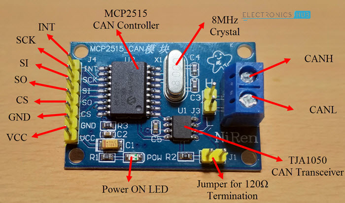
The module used in the project is shown in the image below.
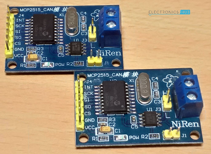
This particular module is based on MCP2515 CAN Controller IC and TJA1050 CAN Transceiver IC. The MCP2515 IC is a standalone CAN Controller and has integrated SPI Interface for communication with microcontrollers.
Coming to the TJA1050 IC, it acts as an interface between the MCP2515 CAN Controller IC and the Physical CAN Bus.
The following image shows the components and pins on a typical MCP2515 Module.
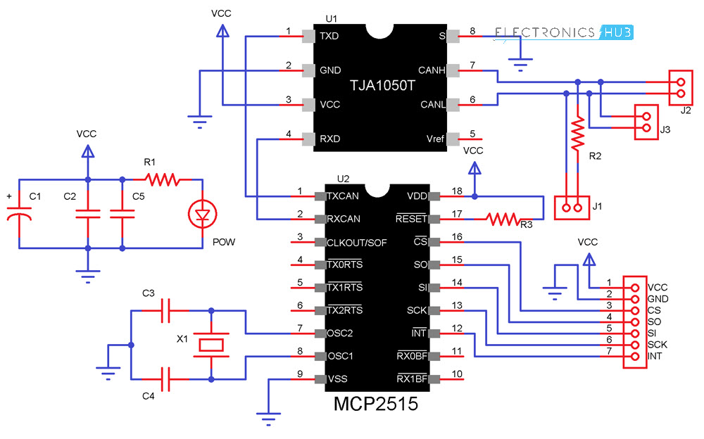
Schematic of MCP2515 CAN Bus Module
Before seeing the schematic of the module, you need to understand a couple of things about both the ICs i.e. MCP2515 and TJA1050.
MCP2515 IC is the main controller that internally consists of three main subcomponents: The CAN Module, the Control Logic and the SPI Block.
CAN Module is responsible for transmitting and receiving messages on the CAN Bus. Control Logic handles the setup and operation of the MCP2515 by interfacing all the blocks. The SPI Block is responsible for the SPI Communication interface.
Coming to the TJA1050 IC, since it acts as an interface between MCP2515 CAN Controller and the physical CAN Bus, this IC is responsible for taking the data from the controller and relaying it on to the bus.
The following image shows the schematic of the MCP2515 CAN Module and it shows how MCP2515 IC and TJA1050 IC are connected on the Module.
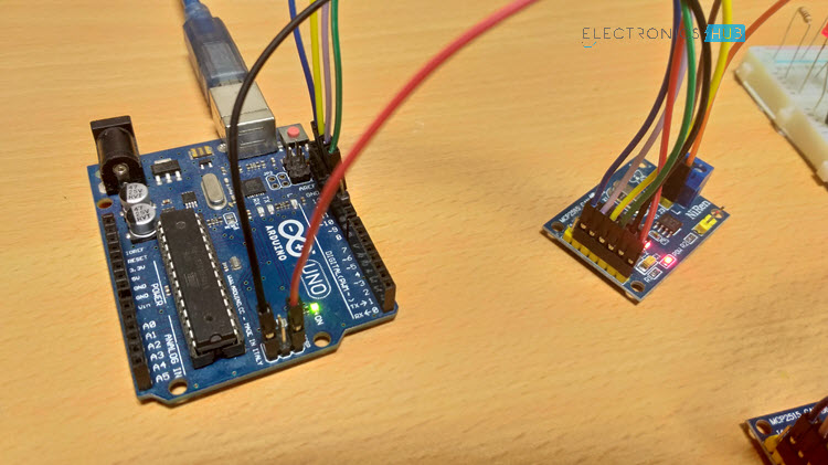
Circuit Diagram for Interfacing MCP2515 with Arduino
The following image shows the circuit diagram of interfacing MCP2515 CAN Module with Arduino and possible communication between two Arduino over CAN Protocol.

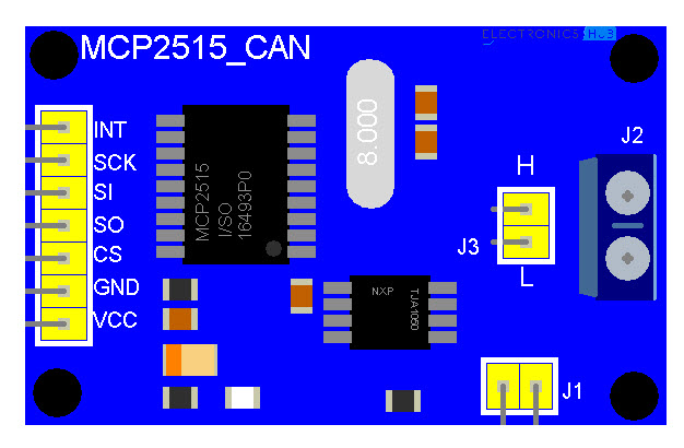
If the pins of the MCP2515 Module are not clear, the following image might be useful.
Components Required
- Arduino UNO x 2
- MCP2515 x 2
- USB Cable x 2
- Connecting Wires
Circuit Design
As mentioned earlier, the CAN Controller IC facilitates SPI Communication Protocol for interfacing with any Microcontroller. Hence, connect the SPI Pin i.e. SCK, MOSI (SI), MISO (SO) and CS of the MCP2515 Module to corresponding SPI Pins of Arduino (see circuit diagram).
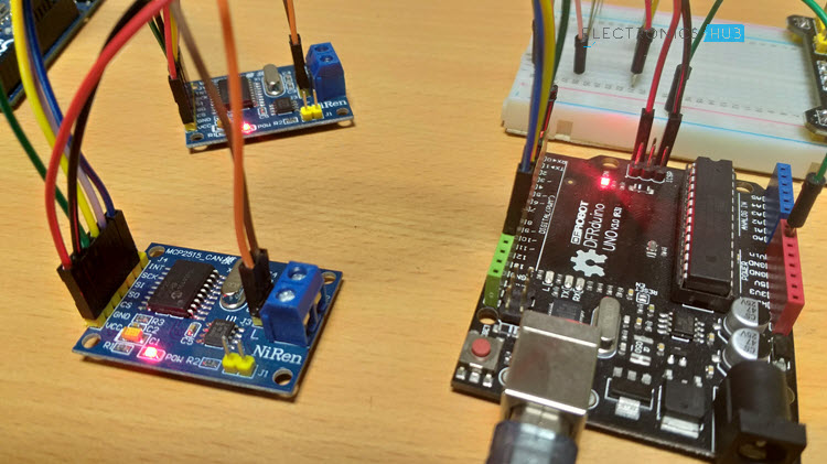
Make two such connections: one pair acts as a transmitter and the other as a receiver. Now for the communication between this transmitter and receiver, connect CANH and CANL pins of each MCP2515 Module.
Code
Before going into the code, you need to download a library for the MCP2515 Module. There are many libraries but I have used this particular one.
Download it and place the extracted contents in the libraries directory of Arduino.
Since the communication involves a Transmitter Module and a Receiver Module, the code is also divided into Transmitter Code and Receiver Code.
Transmitter Code
Receiver Code
Working
Working of this project is very simple as all the work is done by the libraries (SPI and CAN). Since CAN is message-based communication, you need to send a message anywhere between 0 and 8 bytes.
In this project, the transmitter is sending a message as 1 1 2 3 0 5 6 7. This message is transmitted over CAN Bus and the receiver receives this message and is displayed on its serial monitor.
Additionally, the 0th and 4th bit i.e. 1 and 0 in the above sequence are extracted separately by the receiver and turns ON and OFF the LED connected to Pin 2 of Arduino.
Applications
As mentioned in the introduction, CAN is widely used in the field of automobiles. Some of the applications include:
- Electronic Gear Shift System
- Main Interface in Automation (like industrial)
- Medical Equipment
- Robotics
- Auto Start/Stop of Car Engine
The post Arduino MCP2515 CAN Bus Interface Tutorial appeared first on Electronics Hub.
from Electronics Hub https://ift.tt/2N9enzf
Subscribe to:
Posts (Atom)