In this project, we will learn about the MCP2515 CAN Controller Module, how to interface the MCP2515 CAN Bus Controller with Arduino and finally how to enable communication between two Arduino board with the help of two MCP2515 CAN Controllers and the CAN Protocol.
Introduction
Controlled Area Network of simple CAN is a bus standard that allows a Microcontroller and its peripheral devices to communicate without the need of a host device or a computer.
Developed by Robert Bosch GmbH, CAN is protocol is main used in automobiles for communication between a control unit and its components.
For example, the Engine Control Unit is a major control using in a car. This unit is connected to many sensors and actuators like air flow, pressure, temperature, valve control, motors for air control etc. The communication between these modules and the control unit is through CAN Bus.
In order to understand a little bit more about CAN Bus, CAN Controller and other important aspects, the MCP2515 CAN Bus Controller Module is very helpful.
Also read: BASICS OF SPI COMMUNICATION.
A Brief Note on MCP2515 CAN Bus Controller Module
The MCP2515 CAN Bus Controller is a simple Module that supports CAN Protocol version 2.0B and can be used for communication at 1Mbps. In order to setup a complete communication system, you will need two CAN Bus Module.
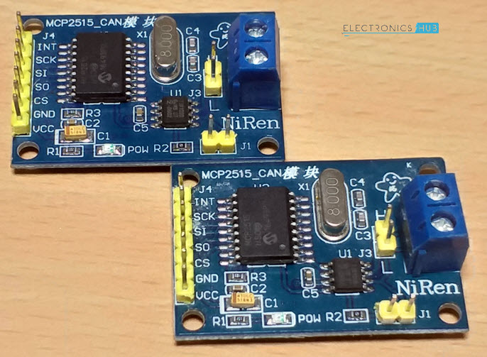
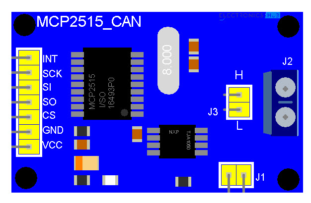
The module used in the project is shown in the image below.
This particular module is based on MCP2515 CAN Controller IC and TJA1050 CAN Transceiver IC. The MCP2515 IC is a standalone CAN Controller and has integrated SPI Interface for communication with microcontrollers.
Coming to the TJA1050 IC, it acts as an interface between the MCP2515 CAN Controller IC and the Physical CAN Bus.
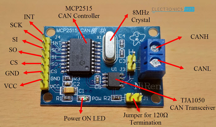
The following image shows the components and pins on a typical MCP2515 Module.
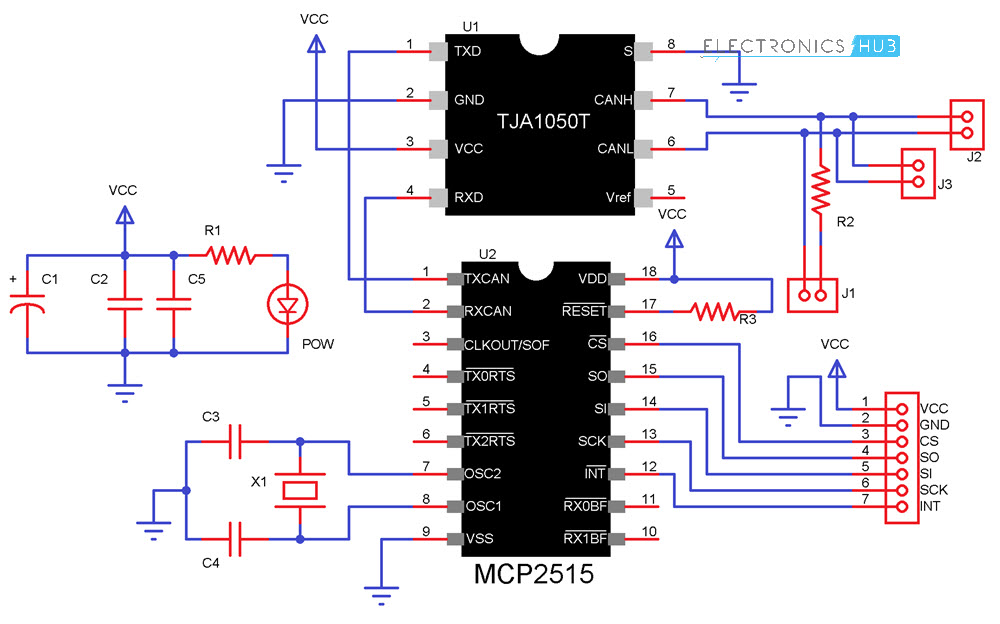
Schematic of MCP2515 CAN Bus Module
Before seeing the schematic of the module, you need to understand a couple of things about both the ICs i.e. MCP2515 and TJA1050.
MCP2515 IC is the main controller that internally consists of three main subcomponents: The CAN Module, the Control Logic and the SPI Block.
CAN Module is responsible for transmitting and receiving messages on the CAN Bus. Control Logic handles the setup and operation of the MCP2515 by interfacing all the blocks. The SPI Block is responsible for the SPI Communication interface.
Coming to the TJA1050 IC, since it acts as an interface between MCP2515 CAN Controller and the physical CAN Bus, this IC is responsible for taking the data from the controller and relaying it on to the bus.
The following image shows the schematic of the MCP2515 CAN Module and it shows how MCP2515 IC and TJA1050 IC are connected on the Module.
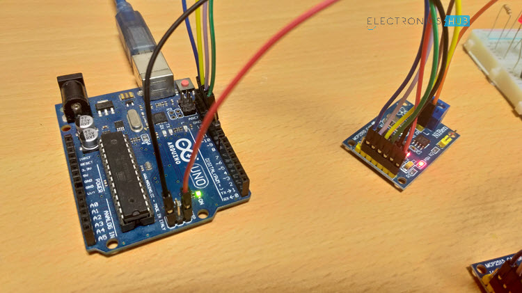
Circuit Diagram for Interfacing MCP2515 with Arduino
The following image shows the circuit diagram of interfacing MCP2515 CAN Module with Arduino and possible communication between two Arduino over CAN Protocol.

If the pins of the MCP2515 Module are not clear, the following image might be useful.
Components Required
- Arduino UNO x 2
- MCP2515 x 2
- USB Cable x 2
- Connecting Wires
Circuit Design
As mentioned earlier, the CAN Controller IC facilitates SPI Communication Protocol for interfacing with any Microcontroller. Hence, connect the SPI Pin i.e. SCK, MOSI (SI), MISO (SO) and CS of the MCP2515 Module to corresponding SPI Pins of Arduino (see circuit diagram).
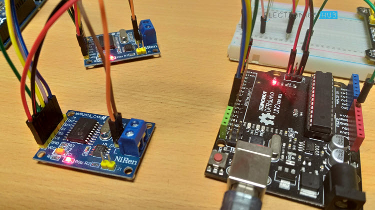
Make two such connections: one pair acts as a transmitter and the other as a receiver. Now for the communication between this transmitter and receiver, connect CANH and CANL pins of each MCP2515 Module.
Code
Before going into the code, you need to download a library for the MCP2515 Module. There are many libraries but I have used this particular one.
Download it and place the extracted contents in the libraries directory of Arduino.
Since the communication involves a Transmitter Module and a Receiver Module, the code is also divided into Transmitter Code and Receiver Code.
Transmitter Code
Receiver Code
Working
Working of this project is very simple as all the work is done by the libraries (SPI and CAN). Since CAN is message-based communication, you need to send a message anywhere between 0 and 8 bytes.
In this project, the transmitter is sending a message as 1 1 2 3 0 5 6 7. This message is transmitted over CAN Bus and the receiver receives this message and is displayed on its serial monitor.
Additionally, the 0th and 4th bit i.e. 1 and 0 in the above sequence are extracted separately by the receiver and turns ON and OFF the LED connected to Pin 2 of Arduino.
Applications
As mentioned in the introduction, CAN is widely used in the field of automobiles. Some of the applications include:
- Electronic Gear Shift System
- Main Interface in Automation (like industrial)
- Medical Equipment
- Robotics
- Auto Start/Stop of Car Engine
The post Arduino MCP2515 CAN Bus Interface Tutorial appeared first on Electronics Hub.
from Electronics Hub https://ift.tt/2N9enzf
No comments:
Post a Comment