In this tutorial, we will learn about electric motors, what is Variable Frequency Drive, working of Adjustable Frequency Drive system and benefits of using VFD in industrial process control.
Introduction
Electric Motors are the workhorses of industries. They convert electrical energy to mechanical energy with very high efficiency. Electric Motors cover the majority of energy consumers and so are the range of applications ranging from industrial manufacturing and processing to commercial and domestic environment.
Some of the common applications of electric motors are pumps, fans, mixers, compressors, conveyors, mills, cranes, cars, machine tools, etc. It is not at all surprising to see such wide range of applications of electric motors considering their low cost, high reliability and simplicity.
Basically, all AC Induction Motors are constant speed machines when run through the main power supply (with appropriate starter mechanism). In fact, the difference in speed from load to full load is at the maximum of 5%.
It is often desirable to operate a motor at variable speeds for various purpose like saving energy, improving efficiency, controlling the torque of the process, etc. Automation of industrial processes has led to Variable Speed Drives of AC Motors.
Variable Frequency Drive (VFD) is a technique often used to achieve the adjustable speed drive of AC motors to control its speed as well as torque.
Need for Variable Speed Drives
Before going into the details of variable frequency drive system, let us take a look at the need for variable speed operation of an electric motor.
As mentioned earlier, all AC motors are constant speed machines and the applications of such fixed speed motors are numerous, like conveyors, dampers, valves, etc. for example. But the need for speed and torque control of electric motors is also essential.
Consider the simple example of an electric car. Today, many car manufacturers are making all electric vehicles that run on batteries and an electric motor, after the success of Tesla. It is obvious that the speed of the car must be constantly controlled by the driver depending on the traffic conditions, speed limits, highways, etc. to avoid collision.
This means that the car must be start, accelerate, decelerate, and stop when ever required. Depending how much the accelerator pedal is pressed, the speed of the car varies. This integral part of our life (or at least those who own an electric car) is essentially a Variable Speed Control system.
In the above example, the need for controlling the speed and torque of the motor are very essential. Another important need for variable speed drives like VFDs is to save a substantial amount of energy, as electric motors are one of the major energy consumers in industries and having an efficient process is very important.
IMPORTANT NOTE: All the electric motors mentioned in this tutorial are 3-phase AC Motors (usually, squirrel cage motors), unless otherwise specified.
Types of Variable Speed Drive
Variable speed drive can be achieved in many ways. The following is a list of the three major variable speed drive categories and some of the methods used in each category.
Mechanical Variable Speed Drive
- Belt or chain drive systems with adjustable sheave diameters.
- Metallic Friction Drives
Hydraulic Variable Speed Drive
- Hydrostatic Drive Types
- Hydrodynamic Drive Types
Electromagnetic
- Eddy Current Coupling
Electrical Variable Speed Drive
- Schrage motor (AC commutator motor)
- Ward-Leonard system (AC motor – DC generator – DC motor)
- Variable voltage DC converter with DC motor
- Variable Frequency converter with AC motor
- Slip control with wound rotor induction motor (slipring motor)
- Cycloconverter with AC motor
- Positioning drives (servo and stepper motors)
What is Variable Frequency Drive (VFD)?
The Variable Frequency Drive or simply VFD is one of the commonly used techniques for controlling the speed of an electric motor. In this technique, power electronic devices are used to vary the frequency of the input power to the electric motor by a technique called Pulse Width Modulation (PWM) and thereby controlling the speed of the motor.
VFD system, using PWM, is capable of adjusting both the speed and torque of an electric motor and therefore provides a continuous range of process speed control.
A Variable Frequency Drive system is also known as Adjustable Frequency Drive (AFD) or Variable Speed Drive (VSD) or Variable Voltage Variable Frequency (VVVF) Drive. It is a simple device that controls the voltage and frequency of the input power of a motor and therefore controls speed of the motor as well as the system being driven by the motor.
Main Components of VFDs
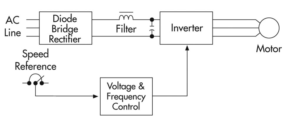
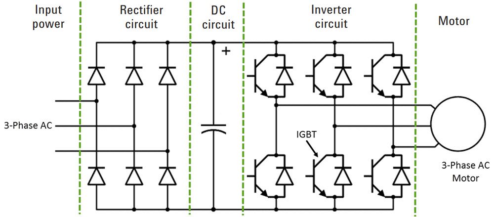
The following image shows a simple overview of a VFD system. It consists of three main components:
- Rectifier Circuit
- DC Circuit Unit
- PWM Inverter Circuit
We will see more about these components in the working but I will give a brief note on each.
Rectifier Circuit
It is used to convert the input AC power to intermediate DC Power.
DC Circuit Unit (DC Bus)
The intermediate DC Power is filtered and stored in high power capacitors.
PWM Inverter Circuit
The inverter unit converts the intermediate DC power into sinusoidal 3-phase AC power using PWM technique.
Working of Variable Frequency Drive System
Even though frequency-controlled method of changing the speed of an AC Motor is a well-known technique, it is only recently that this technique has gained wide spread use and popularity.
In spite of the high cost, complexity and maintenance of DC Motors, they were frequently used in almost all variable speed drive applications. But the development in semiconductors, especially in power electronics and the low cost of squirrel cage AC Induction motor (compared to a DC Motor) has attracted AC Drives.
Using various techniques like VFD for example, you can not only control the speed of an AC Motor but also its torque. The fundamental principle in AC variable speed drive is very simple and we can understand it by starting with the AC Motor itself.
In a simple squirrel cage AC Induction Motor, the rotor windings intersect the rotating magnetic field generated by the stator windings.
The synchronous speed of an AC Motor i.e. speed of the stator’s magnetic field is slightly higher than that of the rotor at full load. This is essential for the rotation of the rotor. The lag between the speed of the rotor and the speed of the magnetic field is known as “Slip” of the motor and torque of the motor is directly proportional to the slip.
Coming to the Synchronous Speed of the motor i.e. the speed at with stator’s magnetic field rotates is dependent on the number of poles in the stator as well as the frequency of the supply current.
Synchronous Speed = (120 x Frequency) / (No. of Poles)
PWM Variable Frequency Drive
When the AC Induction motor is operated at a constant frequency power source, usually 50Hz or 60Hz, the speed of the motor is fixed. A variable frequency drive system, as the name suggests, controls the speed of an AC Induction Motor by varying the frequency of the power supply.
A VFD must also regulate the output voltage according to the frequency so that the output voltage to frequency (V/Hz) is more or less constant, which is a basic characteristic of an AC motor to produce constant torque.
So, the first step of VFD is to convert the 3-phase AC Power to DC Power using (DC voltage and current) using simple diode rectifier circuit. The rectified DC Power contains voltage ripples, which smoothed using filter capacitors before being fed to the inverter. This section of the VFD is known as DC Link Circuit.
The DC voltage must then be converted back to AC with variable voltage and frequency. This is done using power electronic devices like integrated gate bipolar transistors or simply IGBT power transistors using Pulse Width Modulation (PWM).
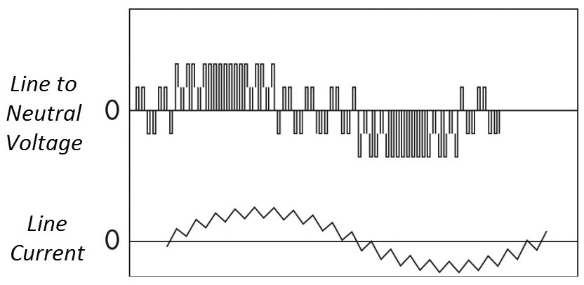
Output voltage is turned ON and OFF at a high frequency and the duration of on-off time i.e. the pulse width is controlled using a control unit (usually a Microcontroller) to approximate a sinusoidal wave (known as quasi sinusoidal wave).
The entire process is usually monitored by a control unit consisting of an MCU (Microcontroller or Microprocessor). The job of a microcontroller is to:
- Monitor the incoming supply voltage.
- Set speed of the motor.
- Monitor DC Link voltage.
- Check that the output current and voltage are within the reasonable limit.
Benefits of VFD
The following are the benefits of using VFDs in HVAC systems. Other applications will also have a similar set of benefits.
A typical HVAC system consists of fans, pumps, compressors, air handlers and chillers. All the motor related devices can have the following benefits when used with a variable speed drive system.
- Simple installation and maintenance.
- Low motor starting current.
- Energy savings.
- Reduced mechanical and thermal stress on motors and belts during start.
- High power factor and low KVA.
The post Variable Frequency Drive (VFD) System | Need, Working, Benefits appeared first on Electronics Hub.
from Electronics Hub http://bit.ly/2QeRYTD


No comments:
Post a Comment