In this project, we will learn about Hall Effect Sensor, how a Hall Effect IC works, block diagram of a typical Hall Effect IC and how to interface a Hall Effect Sensor with Arduino. Additionally, I will show you how to control a Relay using Hall Effect Sensor and Arduino.
Introduction
If you remember the Arduino WaterFlow Sensor Tutorial we implemented earlier, the main component of the Water Flow Sensor is the Hall Effect IC.
A Hall Effect Sensor works on the principle of, well, Hall Effect. Simply speaking, a Hall Effect Sensor or IC detects motion, position or change in magnetic field strength of either a permanent magnet, an electromagnet or any ferromagnetic material.
Hall Effect IC are contact-less magnetically activated switches. They are used in a wide range of applications like automobiles, computers, control systems, security systems etc.
So, in this project, I will discuss about a Hall Effect IC A11004, how this Hall Effect Sensor works and finally how to interface a Hall Effect Sensor with Arduino.
A Brief Note on Hall Effect Sensor
As mentioned earlier, a Hall Effect Sensor is a magnetically activated switch with non-contact trigger. The Hall Effect IC which I will be focusing on in this project is A1104 from Allegro Micro Systems. It is available in 3-pin SIP as well as SOT23 packages.
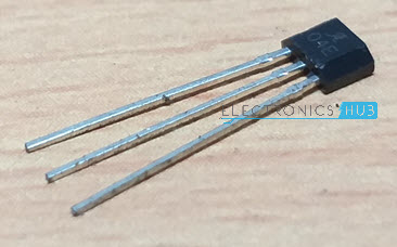
Above image shows the A1104 Hall Effect IC used in this project. It is based on BiCMOS technology, which combines the benefits of both the Bipolar and CMOS technologies.
Block Diagram of the Hall Effect Sensor
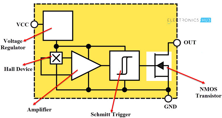
The main components of the A1104 Hall Effect IC are: Voltage Regulator, Hall Device, Small Signal Amplifier, Schmitt Trigger and an Output NMOS Transistor. The following image shows the block diagram of this Hall Effect IC.
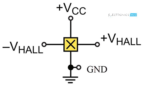
Pins of A1104 Hall Effect Sensor
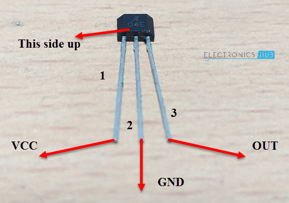
Before going to see the working of a Hall Effect IC, let me give an overview of the Pins of the A1104 Hall Effect IC. There are three pins on the A1104 Hall Effect IC: VCC, GND and OUT.
- VCC (1): Power Supply to IC. 3.8V to 24V.
- GND (2): Ground.
- OUT (3): Output of the IC.
The following image shows the Pins of the A1104 Hall Effect IC.
Working of the Hall Effect Sensor
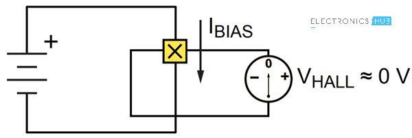
The Hall Element or the Hall Device (sometimes called as the Active Area) is a small semiconductor sheet. This is represented as the following image.
When a constant voltage is given at VCC, some small but constant current flows through the semiconductor sheet. When there is no magnetic field, the voltage VHALL, which is measured across the width of the Hall Element (semiconductor sheet) will be approximately equal to 0V.
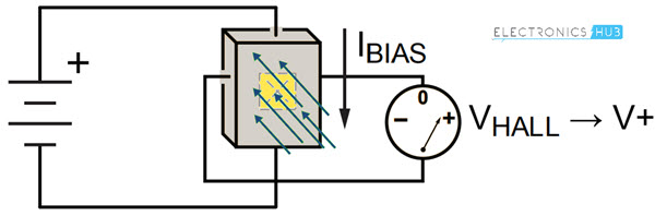
If the Hall Element is subjected to a magnetic field such that, the magnetic flux of the magnetic field is perpendicular to the current flowing through the sheet, the output voltage VHALL is directly proportional to the strength of the magnetic field.
Types of Hall Devices
Based on the orientation and characteristics of the Active Area (Hall Element), Hall Effect Sensors can be categorized into three types.
- Planar Hall Device
- Vertical Hall Device
- 3D Hall Device
In Planar Hall Devices, the flux lines of the magnetic field must pass perpendicularly through the active area to optimally operate the switch. Here, the active area is parallel to the branded face of the IC i.e. the face marked with Manufacturer part number.
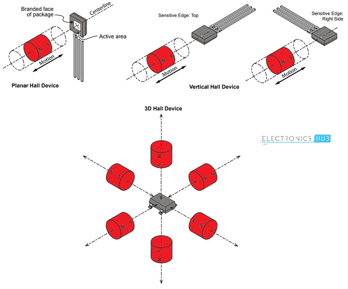
Coming to the Vertical Hall Device, its sensitive areas can be on the top edge, right side edge or left side edge. Finally, a 3D Hall Device can detect the magnetic field when the magnet is approached from any direction.
NOTE: An important point to remember about the operation of the Hall Effect Sensor is that both the magnetic field strength as well as the polarity (North or South) are equally important. The Hall Effect Sensor will switch only if it is subjected a sufficient magnetic flux density as well correct polarity.
A Hall Effect Sensor can be sensitive to either North Pole or South Pole but not both.
Interfacing Hall Effect Sensor with Arduino
Now that we have seen a little bit about the Hall Effect Sensor, let me take you through the steps of interfacing a Hall Effect Sensor with Arduino.
As usual, I will implement two circuits: one is the basic hook-up guide of Hall Effect Sensor with Arduino and the second one is an application circuit where I will control a relay with the help of Hall Effect Sensor and Arduino.
Components Required
The components required for both these circuits are mentioned below.
- Arduino UNO
- A1104 Hall Effect IC
- 10KΩ Resistor
- LED
- 1KΩ Resistor
- 5V Relay Module
- Mini Breadboard
- Connecting Wires
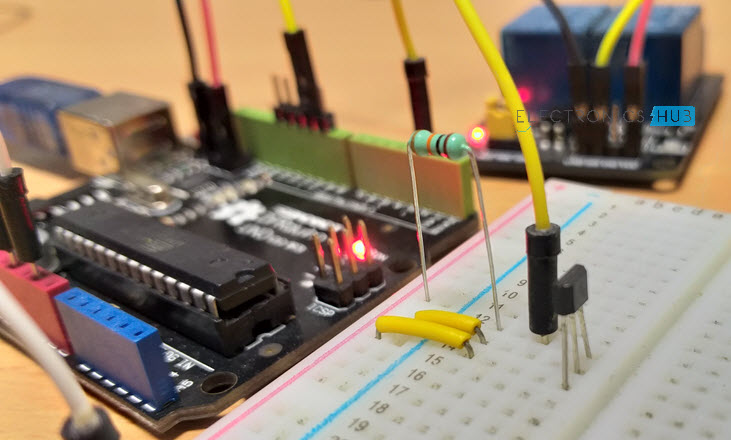
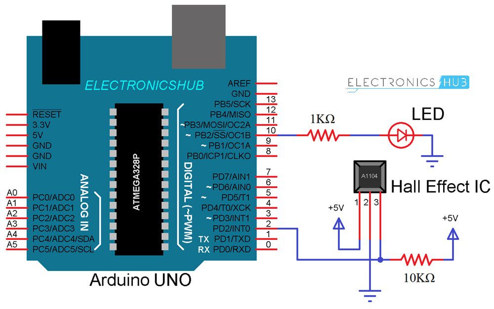
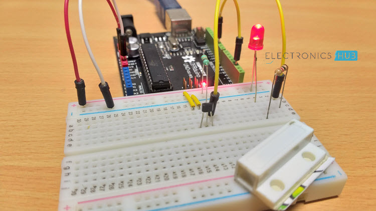
Hook-up Guide of Hall Effect Sensor with Arduino
The following image shows the necessary connections between Arduino UNO and A1104 Hall Effect IC.
Code
Working
If you notice the circuit diagram, the connections are pretty straight forward. The VCC and GND pins of the Hall Effect IC i.e. Pins 1 and 2 from the branding face are connected to +5V and GND of Arduino.
The OUT pin of the Hall Effect IC is pulled HIGH using a 10KΩ Resistor.
Whenever the magnetic field is placed near the Hall Effect IC, the output of the Hall Effect IC becomes LOW. This change is detected by Arduino and accordingly it activates the LED.
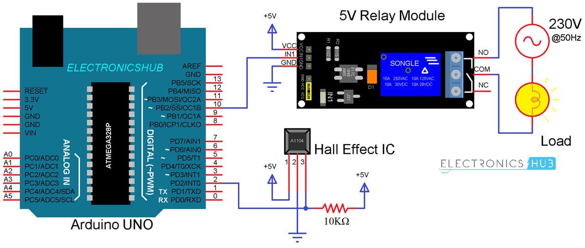
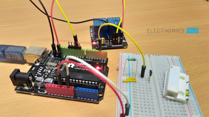
Control a Relay with Arduino and Hall Effect Sensor
The circuit diagram for controlling a 5V Relay Module with Hall Effect Sensor and Arduino is shown below.
Code
Working
The working of this circuit is very simple. Whenever the Hall Effect Sensor is subjected to a magnetic field, it toggles the Relay (as per the code).
Applications of Hall Effect Sensor
Hall Effect Sensor is used in a wide range of applications like
- Automobile ignition systems
- Tachometers
- Current Sensors
- Brushless DC Motor Controllers
- Speed Control Systems
- Printers
- Keyboards
- Switches (key and push button)
- Security Systems
- Position Detectors
The post How to use Hall Effect Sensor with Arduino? appeared first on Electronics Hub.
from Electronics Hub https://ift.tt/2uVyLNe
No comments:
Post a Comment