In this tutorial we will learn how to build an Arduino wireless network, composed of multiple NR24L01 transceiver modules. You can watch the following video or read the written tutorial below.
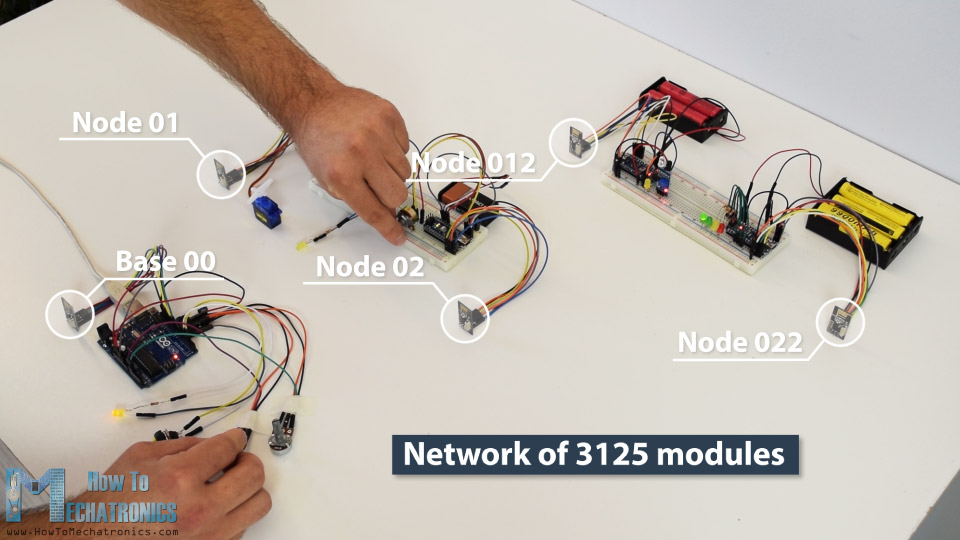
As an example I made a network of 5 nodes and each of them can communicate with any node in the network and at the same time they can work as both transmitters and receivers. This example is actually set up in a way that explains how to make a much larger network, or to be precise, we can have a total of 3125 modules communicating to each other on a single RF channel. So let’s take a look how it works.
In my previous tutorials we have already learned how to make a wireless communication between two Arduino boards using the NRF24L01 modules and the RF24 library. Now in addition to this library, we will use the RF24Network library, which enables in an easy way to build a wireless network with many Arduino boards communicating to each other. Here’s how the network topology works.
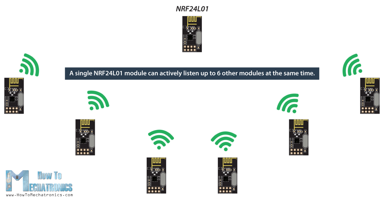
A single NRF24L01 module can actively listen up to 6 other modules at the same time.
This ability is utilized by the RF24Network library to generate a network arranged in a tree topology, where one node is the base, and all other nodes are children of either that node or of another. Each node can have up to 5 children, and this can go 5 levels deep, which means we can create a network of total 3125 nodes. Each node must be defined with a 15-bit address, which precisely describes the position of the node within the tree.
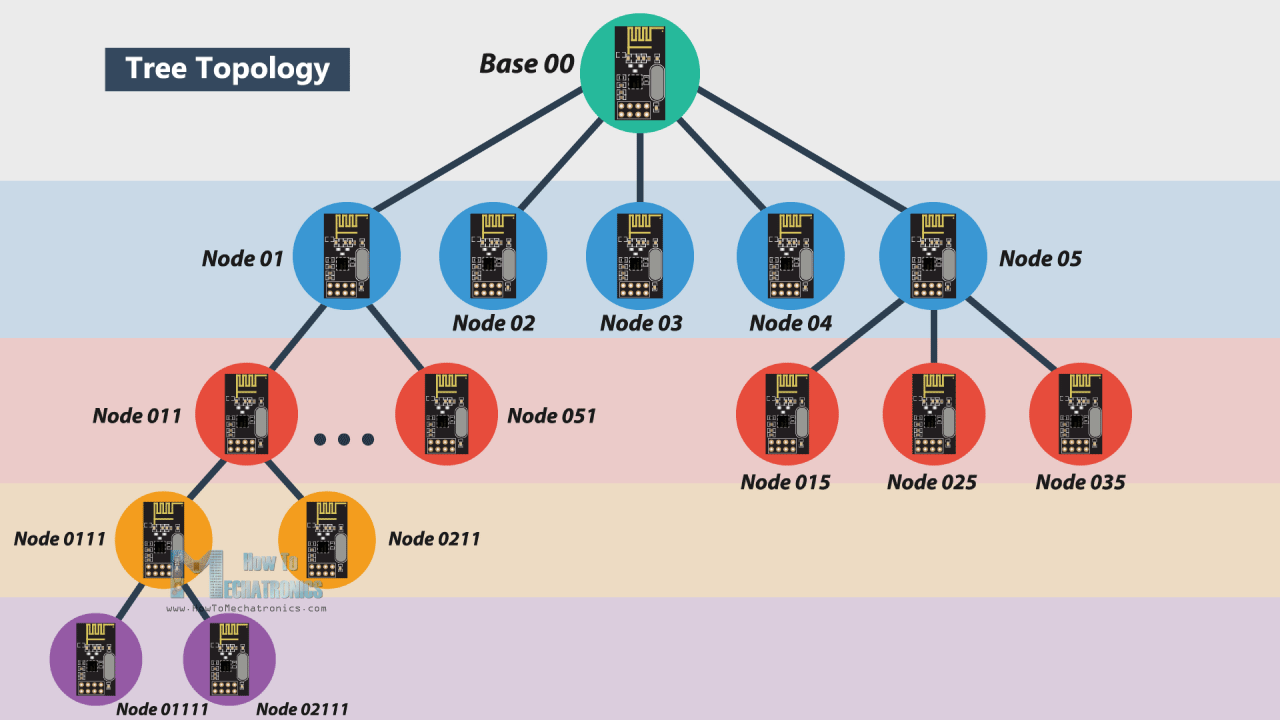
We can actually define the addresses of the nodes in octal format. So, the address of the master or the base is 00, the base children addresses are 01 to 05, the 01 node children addresses are 011 to 051 and so on.
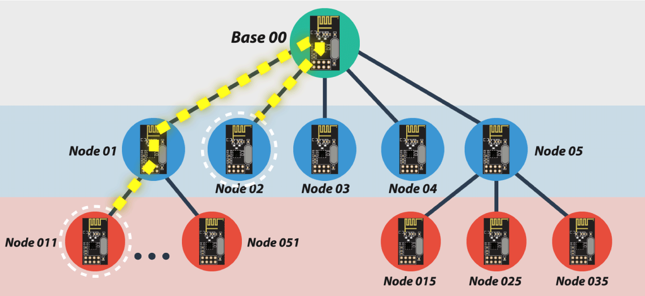
Note that if node 011 wants to talk to the node 02, the communication will have to go through the node 01 and the base node 00, so these two nodes must be active all the time in order the communication to be successful.
Arduino Wireless Servo Motor Control using the RF24Network Library
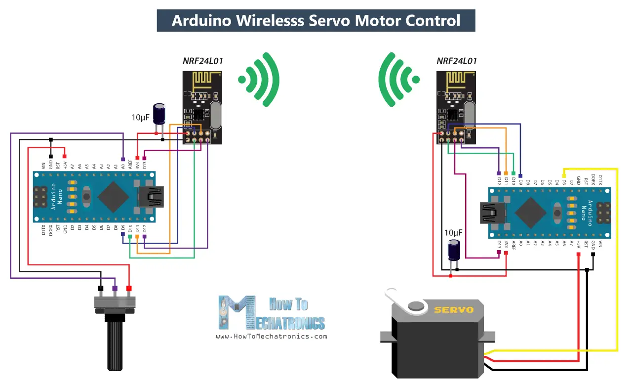
Before we explain the main example of this tutorial, for better understanding how the library works let’s make a simpler example of two Arduinos communicating to each other. Here’s the circuit diagram for this example.
You can get the components needed for this Arduino Tutorial from the links below:
- NRF24L01 Transceiver Module…………. Amazon / Aliexpress
- Arduino Board ………………………………… Amazon / Aliexpress
*Please note: These are affiliate links. I may make a commission if you buy the components through these links.
I would appreciate your support in this way!
So using the potentiometer at the first Arduino we will control the servo motor at the second Arduino. Let’s take a look at the source codes now.
Here’s the code at the potentiometer side:
/*
  Arduino Wireless Network - Multiple NRF24L01 Tutorial
 == Example 01 - Servo Control / Node 00 - Potentiometer ==
  by Dejan, www.HowToMechatronics.com
  Libraries:
  nRF24/RF24, https://github.com/nRF24/RF24
  nRF24/RF24Network, https://github.com/nRF24/RF24Network
*/
#include <RF24.h>
#include <RF24Network.h>
#include <SPI.h>

RF24 radio(10, 9);               // nRF24L01 (CE,CSN)
RF24Network network(radio);      // Include the radio in the network
const uint16_t this_node = 00;   // Address of this node in Octal format ( 04,031, etc)
const uint16_t node01 = 01;

void setup() {
  SPI.begin();
  radio.begin();
  network.begin(90, this_node);  //(channel, node address)
}

void loop() {
  network.update();
  unsigned long potValue = analogRead(A0);  // Read the potentiometer value
  unsigned long angleValue = map(potValue, 0, 1023, 0, 180); // Convert the value to 0-180
  RF24NetworkHeader header(node01);     // (Address where the data is going)
  bool ok = network.write(header, &angleValue, sizeof(angleValue)); // Send the data
}
First we need to include both libraries RF24 and RF24Network, as well as the SPI library. Then we need to create the RF24 object, and include it into the RF24Network object. Here we need define the addresses of the nodes in octal format, or 00 for this node, and 01 for the other node at the servo side.
In the setup section we need to initialize the network, by setting the channel and the address of this node.
In the loop section we constantly need to call the update() function through which all action in the network happens. Then we read the value of the potentiometer and convert it into a value from 0 to 180 which is suitable for the servo control. Then we create a network header where we assign the address of the node where the data is going. At the end, using the write() function we send the data to the other node. So here the first parameter contains the addresses information, the second parameter points which data will be send, and the third parameter is the size of the data.
Here’s the code at the servo side:
/*
  Arduino Wireless Network - Multiple NRF24L01 Tutorial
  == Example 01 - Servo Control / Node 01 - Servo motor ==
*/
#include <RF24.h>
#include <RF24Network.h>
#include <SPI.h>
#include <Servo.h>

RF24 radio(10, 9);               // nRF24L01 (CE,CSN)
RF24Network network(radio);      // Include the radio in the network
const uint16_t this_node = 01;   // Address of our node in Octal format ( 04,031, etc)

Servo myservo;  // create servo object to control a servo

void setup() {
  SPI.begin();
  radio.begin();
  network.begin(90, this_node); //(channel, node address)
  myservo.attach(3);   // (servo pin)
}

void loop() {
  network.update();
  while ( network.available() ) {     // Is there any incoming data?
    RF24NetworkHeader header;
    unsigned long incomingData;
    network.read(header, &incomingData, sizeof(incomingData)); // Read the incoming data
    myservo.write(incomingData);  // tell servo to go to a particular angle
  }
}
On the other side, at the servo motor, we need to define the libraries and the objects in the same way as explained earlier. Here the address of this node in octal format is 01. After defining the servo motor, in the loop section, using the while() loop and the available() function we constantly check whether there is any incoming data. If true, we create a network header through which the data will be accepted and also a variable where the data will be stored. Then using the read() function we read the data, and store it into the incomingData variable. At the end we use this data to move the servo motor according to the potentiometer from the other node.
Arduino Wireless Network with Multiple NRF24L01 Modules
After understanding this example we can move on with the main example of this tutorial and build a wireless network of 5 Arduinos communicating to each other. Here’s a block diagram of the example.
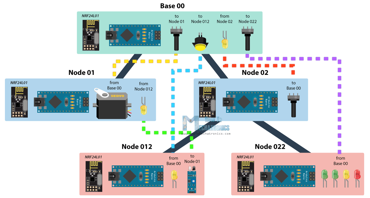
So from the base, using a potentiometer we will control the servo motor at the node 01, with the second potentiometer we will control the LEDs at the node 022, using the button we will control the LED at node 012, and the LED here at the base will be control using the potentiometer at node 02. Also using the infrared sensor at the node 012 we will control the LED at node 01. So we can notice that this example explains how to both transmit and receive data at the same time, as well as how to communicate with nodes from different branches. Let’s take a look at the Arduino codes now.
Base 00 source code
/*
  Arduino Wireless Network - Multiple NRF24L01 Tutorial
          == Base/ Master Node 00==
  by Dejan, www.HowToMechatronics.com
  Libraries:
  nRF24/RF24, https://github.com/nRF24/RF24
  nRF24/RF24Network, https://github.com/nRF24/RF24Network
*/

#include <RF24Network.h>
#include <RF24.h>
#include <SPI.h>

#define button 2
#define led 3

RF24 radio(10, 9);               // nRF24L01 (CE,CSN)
RF24Network network(radio);      // Include the radio in the network
const uint16_t this_node = 00;   // Address of this node in Octal format ( 04,031, etc)
const uint16_t node01 = 01;      // Address of the other node in Octal format
const uint16_t node012 = 012;
const uint16_t node022 = 022;

void setup() {
  SPI.begin();
  radio.begin();
  network.begin(90, this_node);  //(channel, node address)
  radio.setDataRate(RF24_2MBPS);
  pinMode(button, INPUT_PULLUP);
  pinMode(led, OUTPUT);
}

void loop() {
  network.update();
  //===== Receiving =====//
  while ( network.available() ) {     // Is there any incoming data?
    RF24NetworkHeader header;
    unsigned long incomingData;
    network.read(header, &incomingData, sizeof(incomingData)); // Read the incoming data
    analogWrite(led, incomingData);    // PWM output to LED 01 (dimming)
  }
  //===== Sending =====//
  // Servo control at Node 01
  unsigned long potValue = analogRead(A0);
  unsigned long angleValue = map(potValue, 0, 1023, 0, 180); // Suitable for servo control
  RF24NetworkHeader header2(node01);     // (Address where the data is going)
  bool ok = network.write(header2, &angleValue, sizeof(angleValue)); // Send the data

  // LED Control at Node 012
  unsigned long buttonState = digitalRead(button);
  RF24NetworkHeader header4(node012);    // (Address where the data is going)
  bool ok3 = network.write(header4, &buttonState, sizeof(buttonState)); // Send the data

  // LEDs control at Node 022
  unsigned long pot2Value = analogRead(A1);
  RF24NetworkHeader header3(node022);    // (Address where the data is going)
  bool ok2 = network.write(header3, &pot2Value, sizeof(pot2Value)); // Send the data
}
So at the base or the master node we need to define the libraries and the objects as explained earlier, and also define all other nodes to which the master will send data. In the loop section we start by constantly checking whether there is any incoming data. If so, we read the data, store it into the incomingData variable and use it to control the LED brightness. This data is actually coming from the potentiometer from node 02. If we take a look at its code, we can notice that setup is pretty much the same. The important thing is to assign the right address to where we want to send data. In this case, that’s the master 00. So after reading the potentiometer value and converting it into suitable PWM value from 0 to 255, we send this data to the master. We can notice here that I used the millis() function send the data at intervals of 10 milliseconds.
Node 02 source code
/*
  Arduino Wireless Network - Multiple NRF24L01 Tutorial
        == Node 02 (Child of Master node 00) ==
*/

#include <RF24Network.h>
#include <RF24.h>
#include <SPI.h>

RF24 radio(10, 9);               // nRF24L01 (CE,CSN)
RF24Network network(radio);      // Include the radio in the network
const uint16_t this_node = 02;   // Address of our node in Octal format ( 04,031, etc)
const uint16_t master00 = 00;    // Address of the other node in Octal format

const unsigned long interval = 10;  //ms  // How often to send data to the other unit
unsigned long last_sent;            // When did we last send?

void setup() {
  SPI.begin();
  radio.begin();
  network.begin(90, this_node);  //(channel, node address)
  radio.setDataRate(RF24_2MBPS);
}

void loop() {
  network.update();
  //===== Sending =====//
  unsigned long now = millis();
  if (now - last_sent >= interval) {   // If it's time to send a data, send it!
    last_sent = now;
    unsigned long potValue = analogRead(A0);
    unsigned long ledBrightness = map(potValue, 0, 1023, 0, 255);
    RF24NetworkHeader header(master00);   // (Address where the data is going)
    bool ok = network.write(header, &ledBrightness, sizeof(ledBrightness)); // Send the data
  }
}
Next, from the master, we send the potentiometer data to the node 01 for controlling the servo motor.
Node 01 source code
/*
  Arduino Wireless Network - Multiple NRF24L01 Tutorial
        == Node 02 (Child of Master node 00) ==
*/

#include <RF24Network.h>
#include <RF24.h>
#include <SPI.h>
#include <Servo.h>

#define led 2

RF24 radio(10, 9);               // nRF24L01 (CE,CSN)
RF24Network network(radio);      // Include the radio in the network
const uint16_t this_node = 01;   // Address of our node in Octal format ( 04,031, etc)
const uint16_t master00 = 00;    // Address of the other node in Octal format

Servo myservo;  // create servo object to control a servo

void setup() {
  SPI.begin();
  radio.begin();
  network.begin(90, this_node); //(channel, node address)
  radio.setDataRate(RF24_2MBPS);
  myservo.attach(3);   // (servo pin)
  pinMode(led, OUTPUT);
}

void loop() {
  network.update();
  //===== Receiving =====//
  while ( network.available() ) {     // Is there any incoming data?
    RF24NetworkHeader header;
    unsigned long incomingData;
    network.read(header, &incomingData, sizeof(incomingData)); // Read the incoming data
    if (header.from_node == 0) {    // If data comes from Node 02
      myservo.write(incomingData);  // tell servo to go to a particular angle
    }
    if (header.from_node == 10) {    // If data comes from Node 012
      digitalWrite(led, !incomingData);  // Turn on or off the LED 02
    }
  }
}
The node 01 is actually receiving data from two different nodes, one for the servo control and the other for the LED control which comes from the infrared sensor from the node 012.
Node 012 source code
/*
  Arduino Wireless Network - Multiple NRF24L01 Tutorial
            == Node 012 (child of Node 02)==
*/

#include <RF24Network.h>
#include <RF24.h>
#include <SPI.h>

#define led 2
#define IR 3

RF24 radio(10, 9);               // nRF24L01 (CE,CSN)
RF24Network network(radio);      // Include the radio in the network
const uint16_t this_node = 012;  // Address of our node in Octal format ( 04,031, etc)
const uint16_t node01 = 01;    // Address of the other node in Octal format

void setup() {
  SPI.begin();
  radio.begin();
  network.begin(90, this_node);  //(channel, node address)
  radio.setDataRate(RF24_2MBPS);
  pinMode(led, OUTPUT);
  pinMode(IR, INPUT);
}

void loop() {
  network.update();
  //===== Receiving =====//
  while ( network.available() ) {     // Is there any incoming data?
    RF24NetworkHeader header;
    unsigned long buttonState;
    network.read(header, &buttonState, sizeof(buttonState)); // Read the incoming data
    digitalWrite(led, !buttonState); // Turn on or off the LED
  }
  //===== Sending =====//
  unsigned long irV = digitalRead(IR); // Read IR sensor
  RF24NetworkHeader header8(node01);
  bool ok = network.write(header8, &irV, sizeof(irV)); // Send the data
}
In such a case, we use the header.from_node attribute in order get information from which node does the data come from. In case the incoming data is from the master, we use it to control the servo, and in case the incoming data is from the node 012, we use it to control the LED.
At the node 012 we have both transmitting and receiving. The infrared sensor controls the previously mentioned LED at node 01 and the LED here is control from the button at the master.
Node 022 source code
/*
  Arduino Wireless Network - Multiple NRF24L01 Tutorial
            == Node 022 (child of Node 02)==
*/

#include <RF24Network.h>
#include <RF24.h>
#include <SPI.h>

#define led1 2
#define led2 3
#define led3 4
#define led4 5

RF24 radio(10, 9);               // nRF24L01 (CE,CSN)
RF24Network network(radio);      // Include the radio in the network
const uint16_t this_node = 022;  // Address of our node in Octal format ( 04,031, etc)
const uint16_t master00 = 00;    // Address of the other node in Octal format

void setup() {
  SPI.begin();
  radio.begin();
  network.begin(90, this_node);  //(channel, node address)
  radio.setDataRate(RF24_2MBPS);
  pinMode(led1, OUTPUT);
  pinMode(led2, OUTPUT);
  pinMode(led3, OUTPUT);
  pinMode(led4, OUTPUT);
}

void loop() {
  network.update();
  //===== Receiving =====//
  while ( network.available() ) {     // Is there any incoming data?
    RF24NetworkHeader header;
    unsigned long potValue;
    network.read(header, &potValue, sizeof(potValue)); // Read the incoming data
    // Turn on the LEDs as depending on the incoming value from the potentiometer
    if (potValue > 240) {
      digitalWrite(led1, HIGH);
    } else {
      digitalWrite(led1, LOW);
    }
    if (potValue > 480) {
      digitalWrite(led2, HIGH);
    } else {
      digitalWrite(led2, LOW);
    }
    if (potValue > 720) {
      digitalWrite(led3, HIGH);
    } else {
      digitalWrite(led3, LOW);
    }
    if (potValue > 960) {
      digitalWrite(led4, HIGH);
    } else {
      digitalWrite(led4, LOW);
    }
  }
}
Finally, the LEDs at node 022 are controlled using the data coming from the other potentiometer at the master.
So, to sum up, if everything is connected properly, and all of the nodes are active all the time, our job boils down to just precisely addressing the nodes and all the heavy work behind is carried out by the incredible RF24Network library.
So that would be all, I hope you enjoyed this Arduino project and learned something new. Feel free to ask any question in the comments section below.
The post How To Build an Arduino Wireless Network with Multiple NRF24L01 Modules appeared first on HowToMechatronics.
from HowToMechatronics https://ift.tt/2M2G5x9
No comments:
Post a Comment