Wednesday 20 April 2016

Single IC Organ By IC NE556

Single IC Organ By IC NE556
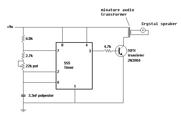
When you will think to build Single IC Organ Circuit the some one. I begs for to advise this circuit , because use IC NE556 or LM556. Which within its structure is like have the integrated circuit IC 555 arrive at 2 together follow my circuit. Control by Keyboard contacts and SW1 Tremolo ON/OFF as a result can choose music pitch that can want.The detail about mini Organ Circuit the this. Can see in circuit picture sir.


ic ne556 pin configuration
ic ne556 datasheet

IC 555 LED Flasher

This is easy LED Flasher circuit. It use IC 555 drive LED display.

A younger brother of me just begin take an interest the electronics. Want to try build Simple LED Flasher Circuit. I then advise this circuit , because of use the integrated circuit timer highly popular type IC NE555 or LM555 very the circuit is Pulse Oscilator the frequency is low. From the circuit will think to use LED 2 pcs wink alternate. Detail , have no chicken many mites. Invite a friend sees in circuit picture better sir


ic 555 led flasher circuit operation of 555 timer led flasher circuit explain the operation of 555 timer led flasher circuit how to use a 555 timer to flash a led 555 timer flashing led projects ne555 flashing led 555 timer led blinker led flasher circuit using ic 555

Door buzzer with 555

This is easy circuit buzzer. It use IC 555, Speaker 25 -80 OHM.

I demolishes a store-room , see old loudspeaker and other equipment a little again. Then born the though builds Door Buzzer by use , IC 555. Perform sound electric bell origin. When press S1 as a result have a voice fair loud. This circuit almost must not do anything. Because divisible Amen! should use 25-80ohm size loudspeakers. will make good sound use force against electricity low work or economize the electricity. You will may use 9V batteries all right sir

Simple Timer by CA3140 + NE555

This be the circuit sets the time to model is simple,at can fix the time had long ago and have tall good accuracy. By use pillar equipment be IC CA3140 for fix time mouth and NE555 perform sound electric bell origin. By we can fine time value done to a turn VR1 can fine since 10 second arrive at 3 hour. When the time expires will have an electric bell that a loudspeaker. For the equipment that should choose specially. Be C1 100uF 16V values should are a kind Tantalum. Because tall quality more Electrolytic. The moderately but if no enough replace can sir. Request friends have fun the circuit sets the time this please sir

LED Chaser by IC 4017 + IC 555

I believes in that extremely amateur electronics many you, may ever build the LED flasher or light blinks or the LED Chaser prevent come to already. Today I begs for to advise the circuit LED Chaser, by have LED show 10 amounts together. blink stick bright chase go to continually. By have IC 4017 precede at drive a tube LED all. Which its work be Counter circuit good just this besides. Still have IC 555 wait for feed Clock with then can fine the speed of the winking with VR1 good easy. The detail is other see in circuit picture better.

Circuit LED Chaser by IC 4017 + IC 555

Table Lamp Circuit by IC 555

If you want Power Lamp Flasher at give electric tall power. As a result try out Table Lamp Circuit the this. It uses the integrated circuit NE555 be pillar equipment. Control the rate blinks of Lamp. Get , for the transistor power make Lamp 12V electric tall power about 20W or use current 1.6A stick bright get. The Q3 can use replace get many the number such as TIP41 or H1061 or MJ3055 or will use 2N3055 numbers all right sir. The detail is other see in the circuit

Circuit Door Buzzer by NE555 + LM386

Someday I goes to visit a friend. He begs me helps to seek electric bell front door circuit. In model to be simple, use the a little equipment. I then choose the Door Buzzer circuit this give. Because of use , IC NE555 produce electric bell sound and use IC LM386 for amplify talk at one time. For R1 use fine decorate the sound as you like it. request have fun this circuit.

Circuit Egg Timer By LM555

This is Easy and Mini Timer Circuit ( Egg Timer) by IC 555.
Alarm by Buzzer.
Circuit Egg Timer by LM555
This be mini timer circuit that interesting. I calls that Circuit Egg Timer. By use integrated highly popular circuit number LM555 or NE555 or the number replaces. By VR1 use control the time of the circuit sets the time. When expire buzzer as a result make a noise warn hear. For S1 use for choose that Time or Stand. The detail is other request friends see in the circuit better sir

British Police Car Siren by IC 555

This month I am making 3 different types of siren circuits based on the 555 timer. The first circuit simulates the siren of a British police car. It uses two 555 timers in the circuit. The 555 on the right is wired as an alarm tone generator and the second 555 timer on the left is a 1 Hz astable multivibrater. The output of the left timer is to frequency modulate the right timer. This causes the right timers frequency to alternate between 440Hz and 550Hz at a 1 Hz cyclic rate. The transistor is used to help strengthen the signal to the speaker.
British Police Car Siren by IC 555

American Police Car Siren by IC 555

The second circuit simulates the siren of an American police car. It uses two 555 timers in the circuit. The 555 on the right is wired as an alarm tone generator and the second 555 timer on the left is wired as a low frequency astable timer which generates a ramp waveform of about 6 seconds that is buffered by the transistor and again used to frequency modulate the tone generator. The transistor is used to help strengthen the signal to the speaker

American Police Car Siren by IC 555

Red Alert Startrek Alarm by IC 555

The third circuit simulates the Red Alert siren from the TV show Star Trek. It uses two 555 timers in the circuit. The 555 on the right is wired as an alarm tone generator and the second 555 timer on the left is wired as a 1.5 second non-symmetrical astable that generates a fast rising but slow falling saw tooth waveform. This waveform is buffered by the transistor and used to frequency modulate the tone generator and making its frequency rise slowly during the falling parts of the saw tooth but collapse rapidly during the rising part of the saw tooth. The output starts as a low frequency, rises for 1.15 seconds to a high tone, ceases for .35 seconds and then repeats the cycle.
Red Alert Startrek Alarm by IC 555

Timer Plus Relay by IC 555

This be Timer Plus Relay Circuit by IC 555. When see the circuit also a little equipment. By the value R1 and C1 perform set the time give Relay work 11 long ago second. When we begin to encourage the circuit by switch press 2 pin with a leg Ground note: Relay 6V 500ohm. Use current 12mA. The detail is other , see in the circuit adds.

IC Digital 555 Pulse Generator

Circuit : Miroslav Adzic – Serbia & Montenegro
Description:
A 555 pulse generator circuit with a difference, the initial pulse is tailored by additional circuitry to match the duration of subsequent pulses.
single pulse gen
IC Digital 555 Pulse Generator
Notes:
The NE555 and the First Pulse
The first positive pulse from a classic 555-based oscillator is always 1.6 times longer than the following pulses. The difference is caused by the fact that only during the first cycle C2 starts charging up from 0 V. This is generally not a problem, but sometimes this first pulse just should be the same length as the rest – at least approximately

Inverts to Negative From Positive Voltage by IC 555

This simple circuit is a good solution to the powering a dual supply op amp from a single battery problem. The circuit simply takes a positive voltage and inverts it. It uses only one 555 timer and a few other passive components, so it doesn’t add much in the way of size and cost to a project.
Voltage Inverter by IC 555
Substitutions
R1 1 24K 1/4 Watt Resistor
R2 1 56K 1/4 Watt Resistor
C1 1 3300pF 25V Ceramic Capacitor
C2 1 47uF 25V Electrolytic Capacitor
C3 1 10uF 25V Electrolytic Capacitor
D1, D2 2 1N4148 Silicon Diode
U1 1 555 Timer
MISC 1 Wire, Board

PWM Speed Motor Controller By IC 555

This 555 timer based PWM controller features almost 0..100%
PWM Speed Motor Controller  By IC 555
This 555 timer based PWM controller features almost 0..100% pulse width regulation using R1,
while keeping the oscillator frequency relatively stable. The frequency is dependent on values of R1 and C1,
values shown will give a frequency range from about 170 to 200 Hz. Any 555 chip will do, CMOS is fine as well.
Diodes are not critical, I used 1N4148. Total cost of parts is about $2. As the whole thing is quite trivial,
it’s very easy to build on prototyping board like I did (as you can see, one of capacitors –
C1 is replaced with different value, 0.047 uF to be precise

lead acid battery Charger 6V -12V By 555 and LM340

Here is circuit lead acid battery Charger 6V -12V.
I use IC 555 and LM340. Read Detail more in image circuit

Relay Timer switch By IC 555 and 741

In Fig.1 see a 100 second delayed turn ON relay RL1 switch, if plug power +12V in circuit. In Fig.2 see a two range 6-60 second and 1-10 minute auto turn off relay timer circuit, with 555.
Part
R1=1 Mohms C4=100nF 63V IC2=LM555
R2=330 Kohms C1-2=100uF 16V RV1=470 Kohms pot.
R3=680 ohms C3=1000uF 16V RL1-2=12V >120 ohms Relay
R4=2.2 Kohms D1=1N4148 S1-2=Push button n.o
R5-7=4.7 Kohms D2-3-4=1N4001 S3=2X2 switch
R6=47 Kohms Q1=BC214
R8-9=22 Kohms IC1=LM741
Relay Timer switch By IC 555 and 741

Generating -5 Volts From a 9 Volt Battery With IC 555

A 555 timer can be used to generate a squarewave to produce a negative voltage relative to the negative battery terminal. When the timer output at pin 3 goes positive, the series 22 uF capacitor charges through the diode (D1) to about 8 volts. When the output switches to ground, the 22 uF cap discharges through the second diode (D2) and charges the 100 uF capacitor to a negative voltage. The negative voltage can rise over several cycles to about -7 volts but is limited by the 5.1 volt zener diode which serves as a regulator. Circuit draws about 6 milliamps from the battery without the zener diode connected and about 18 milliamps connected. Output current available for the load is about 12 milliamps. An additional 5.1 volt zener and 330 ohm resistor could be used to regulate the +9 down to +5 at 12 mA if a symmetrical +/- 5 volt supply is needed. The battery drain would then be around 30 mA

Generating -5 Volts From a 9 Volt Battery With IC 555

OR gate with two IC 555

how to OR gate two 555, when one 555 cycles at a low frequency a valve turns on an off, the second 555 stretches the ON duration of the pulse with a diode OR gate, this OR output uses sample and hold to get the stable analog data from a sensor after the actuator has gone OFF, this ensures correct reading
OR gate with two IC 555

Saturday 16 April 2016

Nagative voltage generation using 555 timer

Nagative voltage generation using 555 timer

This is Circuit build Nagative voltage generation Form IC 555 timer ,It is Hot IC and Easy to Use

Voltage doubler with IC 555

parts:
U1 NE555 timer IC
R1 2.2k ohm resistor
R2 15k ohm resistor
C1 0.01 uF ceramic capacitor
C2, C3 220 uF electrolytic capacitor
C4 470 uF electrolytic capacitor
D1, D2 1N4002 diode
all resistors are 5 or 10 percent tolerance, 1/4-watt
all capacitors are 10 percent tolerance
Voltage doubler with IC 555
this circuit rougly doubles the voltage of the input, however the current output is low. doubled output is at ‘V source

Infrared Remote Control System Receiver

Infrared Remote Control System Receiver By IC Digital
This is a single channel (on / off) universal switch that may be used with any Infra Red remote control that uses wavelengths between 850-950nm.
Notes:
Any “button” of any remote control may be used to work this universal switch. The button must be pressed for two seconds (determined by R3 and C2) before the relay will operate. Once operated the circuit will remain in this state (latched) until reset. To reset, any button is pressed and held for the delay.
For example, if you were watching TV, and your set was tuned to Channel 3, you could press and hold the TV remote controls channel 3 button for two seconds. That way the TV viewing would not be affected and the relay would activate. You can connect anything to the relay, for example a lamp, but make sure that the relay contacts can handle the rated voltage and current.
Circuit Operation:
IC1 is an Infra Red module. IR modulated pulses are received and buffered by this IC. It has a standard TTL output, the output with no signal is logic 1. One gate of a CMOS inverter and drives Red LED1 as a visible switching aid. Another gate buffers the signal and applies it to the time constant circuit, comprising R3,C2,R4 and D1. C2 charges via R3, and discharges via R4, D1 prevents quick discharge via the low output impedance of the CMOS bufferInfrared Remote Control System Receiver By IC Digital

Touch Switch ON-OFF by IC 555

The modern mechanic switches are improved concerning of old technology. We need however many times to replacement some old switch or to check currents bigger than the durability of certain switches or simple we need something with modern appearance. For he and different reasons is essential the up circuit. He is simple in the manufacture and the materials that use they exist everywhere. This based in the known 555, which drives a relay of which the contacts play the role of switch. The metal surfaces can have what form we want, but it should they are clean and near in the circuit. In order to it changes situation it suffices touch soft somebody from the two plates. Plate JF1 in order to the contacts of RL1 close [ON] or plate JF2 in order to the contacts of RL1 open [OFF]. The current that RL1 will check depended from his contacts. The Led D2 turns on when the switch they are in place ON and the contacts of RL1 closed.
Touch Switch ON-OFF by IC 555
Part List
R1-2=3.3M 1/4W 5% D1=1N4148 RL1=12V Relay [Your choise ]
R3=10K 1/4W 5% D2= Red LED 3 or 5mm. JF1-2=Metal Plate
R4=1K 1/4W 5% Q1=BC547
C1=10nF 63V MKT 5% IC1=555

Efficient flyback driver by IC 555 + IRF510

This is a good and fairly efficient flyback driver circuit. All parts can be obtained easily from Radio Shack, including the MOSFET. This circuit uses a 555 timer IC to pulse a 2N2222 with square wave at a frequency that is set by the capacitor and the potentiometers. The 2N2222 then drives the gate of the MOSFET and the MOSFET delivers the pulse to the ten turn winding on the flyback. If you build this circuit you will have to adjust the potentiometers until you get the longest arc possible. The circuit will run from +12VDC to +15VDC at about 3A. The MOSFET must be heatsinked! This is important if you are going to run this for any decent amount of time. If the MOSFET still gets too hot or burns up you can place a 4 ohm (for a +12V supply) or a 5 ohm (for a +15V supply) between the source lead of the MOSFET and the primary on the flyback. Make sure that these resistors havethe proper power rating for the voltage and current that they will be carrying. The flyback should be wound with ten turns of 14-16 guage solid wire. Anchor it in with some electrical tape. Any previous primary windind should have already been removed before winding the new one
Efficient flyback driver circuit by IC 555 + IRF510

Power On Delay Circuits by 555

These circuits will delay the application of power to a second circuit using mechanical relays or transistors. Other output control devices could also be used.
Power On Delay Circuits by 555

Ignition coil driver by IC 555 + 2N3055

Here is a very simple circuit that will provide high voltage (15-40kV) sparks using a common ignition coil. The input is 12VDC at around 5 to 6 amps. Mine produces sparks that are about 3/4″ to 1″ in length. A 2N3055 NPN power transistor is pulsed with a square wave signal that comes from the 555 timer IC. The frequency of the pulses depends on the resistors between pins 7 and 8 and between pins 7 and 6. The pulse is also dependent on the capacitor. You can experiment with these values. Try inserting a smaller capacitor to raise the frequency. At different frequencies the sparks will change certain characteristics. At a high frequency the sparks will get fatter but shorter in length. At lower frequencies the spark maybe longer but thinner. I assembled my project on a solderless breadboard. You can use whatever you like. The capacitor should be a tantalum or mylar type, but this is not absolutely necessary. A ceramic type should work fine just as long as the temperature is not too high around it
Ignition coil driver by IC 555 + 2N3055

SOLID STATE TESLA COIL WITH 555 TIMER

Setting the operating frequency with an integrated timer is easy and practical. Following schematic is nothing more than the standard astable mode circuit design with a classic 555. It requires only two resistors and a capacitor to set frequency (with duty cycle of course) and another resistor to determine power transistor’s base current, which you can find it’s optimal value experimentally. I used 1K for R1, 2.2K for R2, and 10nF for C which made circuit to run nearly at 27 kHz theoretically, at %60 high to %40 low duty cycle. You can quickly calculate operating parameters from the resistance and capacitor values with a small program that I’ve written
SOLID STATE TESLA COIL WITH 555 TIMER

12V input, 12V battery charger by 555,7815

The charger consists of two stages: The first is a capacitive voltage doubler, which uses a 555 timer IC driving a pair of transistors
connected as emitter followers, which in turn drive the voltage doubler proper. The doubler has power resistors built in, which limit the charging current.

The second stage is a voltage regulator, using a 7815 regulator IC. Its output is applied to the battery via a diode, which prevents reverse current and also lowers the voltage a bit. The resulting charge voltage is about 14.4V, which is fine for charging a gelled or AGM battery to full charge, but is too high as a trickle charger, so don’t leave this charger permanently connected to a battery. If you would like to do just that, then add a second diode in series with D3!
There is a LED connected as a charge indicator. It will light when the charge current is higher than about 150mA. The maximum charge current will be roughly 400mA
12V input, 12V battery charger by 555,7815

Flyback Transformer Based high voltage generators

Uses a 555 timer IC to generate a 720Hz triangle waveform (at pin 2 of the IC). This waveform is of about 50% duty cycle. This triangle waveform is compared to a fixed voltage with a comparator, IC2. The fixed voltage can be varied by potentiometer VR1. The output of the comparator is a 720Hz square wave of variable duty cycle. The potentiometer must be adjusted so that Q2 is near to 0% duty cycle (ie it spends the majority of the time off)
Flyback Transformer Based high voltage generators

555 timer pulse generator

To drive ignition coils is to use a 555 timer pulse generator. A 555 generates a square wave output that triggers the 2N3055. Adjusting the two potentiometers and the value of the capacitor will change the frequency of the output.
555 timer pulse generator

Drive SCR thyristor by IC 555

This circuit gives a burst of pulses to fire 2 SCRs, when pin 4 is taken to 12V the SCR is turned on, to use this circuit you need 12V short pulses phase shifted with respect to AC sine wave on bridge.
This way you can control the bridge from near 0% to near 100% ON, that way battery banks can be charged, electroplating can be done, current and voltage can be controlled with opamps, thyristors are very rugged compared to transistors and MOSFETS in that order
Drive SCR thyristor by IC 555

12V to 18V step-up DC converter by IC 555

This is a power source that creates a DC voltage higher than the voltage feeding the it. It might be used to power your laptop (+18V) from a car battery (12V ~ 13.8V). It is built using very ordinary parts that should be readily available. Here are some specs:
Input voltage 9V ~ 15V
Output voltage 12V ~ 25V
Output current Max. 3A @18V
Switching frequency 20kHz – 40kHz
Efficiency 65% – 95%
If you know these circuits, please skip the following. The circuit is a step-up converter, and it’s workings can be explained by the main property of a coil: its inductance. Imagine a current flowing through a coil. The inductance will cause the current to continue running, even if the power supply that caused this current is taken away. The voltage across the coil will take any value required to keep the current running. This is why you can easily create sparks with a coil, a spark is simply a current flowing at a very high voltage.
This circuit flips between two states: ‘charging’ the coil with current, and dumping this current into the output capacitor. The frequency at which this happens is so high that only a small ripple remains at the output capacitor (10000uF). Here is the circuit12V to 18V step-up DC converter by IC 555

100 Seconds Duration On Switch with Touch Control by 555

This is a touch control switch which keeps the circuit on about 100 seconds after touching the plate connected to the 2 numbered pin. At the end of this time duration, relay releases and the circuit gets to off position.
The impedance of the trigger input of the 555 timer IC is very high and the inductive voltage on the human body is enough to trigger it. The circuit works based on this principle. You can use a piece of metal as a plate. The circuit can be used in toy circuits, buzzers or any project that is suitable. You can adjust the duration time by changing the R1 and C1 values
100 Seconds Duration On Switch with Touch Control by 555

12VDC Negative Voltage DC Converter by 555

The circuit is very simple, and is easily made on Veroboard or similar. Construction is not critical, and the schematic is shown in Figure 1 below.
Rectifier diodes should be ultrafast (UF4004 or similar), or you can use 1N4148 signal diodes. Losses will be slightly higher if you use signal diodes, or lower if you wanted to go to the trouble of using Schottky diodes – the latter are not warranted in such a simple circuit (IMO). The zener diode is to protect the circuit against transient overvoltage, and is optional
Using only a standard NE555 timer and a few other parts, this circuit should be up an running in about an hour. The 555 is configured as a minimum parts count astable (i.e. no stable states) multivibrator, and runs at around 17kHz with the values shown. The zener diode (D3) should be a 16V/ 1W type. Resistors are 1/2W carbon film, and small caps may be polyester or mylar
12VDC Negative Voltage DC Converter by 555

A flyback converter high voltage supply by 555

The circuit diagram of the flyback converter will hold no surprises (Fig.16). Literally the only difference with the boost converter is that the inductor is replaced by a transformer, and that the transistor has been replaced for a BUZ21. The BUZ21 has a much lower on resistance (Ron=0.085 ohm) as compared to the BUZ41A (Ron=1.5 ohm) but also a lower drain-source breakdown voltage (100V versus 500V)
A flyback converter high voltage supply by 555

Frequency Divider by 555 and 4040

U1 7555 is a CMOS version of 555 LM555 pdf datasheet.
The 555 here is in Astable Oscillator mode, C1 and C4 are decoupling capacitors 0.1uF value, ceramic disc.
The output is around 100kHz, If C3 is plastic or mica the frequency output will be stable with temperature. It is better to use a crystal oscillator.
The 555 output is fed to clock input of 4040, the output of 555 will be a square wave, on every high to low transition (falling edge or negative transition) the counter increments by one and the output is 12 bit binary.
If input frequency is F the final output at Q12 is F/4096. The period T = 1/F.
If you make the 555 run at 1Hz, C3 around 7uF, Then this circuit becomes a long duration timer, the Q12 period will be 4096 seconds or 68 minutes
Frequency Divider by 555 and 4040

3-6V Xenon Strobe Light by IC 555 and IRF9Z20

This circuit used to come as a kit from a surplus supplier, but probably isn’t available anymore. It shows a few novel concepts such as using a 555 as a pulse width modulator (PWM), and series/parallel camera flash transformers.
The 555 is set up as a pulse width modulator (the off (low) time being set by the trimmer). The output at pin 3 is connected to the gate of the P-channel MOSFET (IRF9Z20) through the 100R resistor to prevent parasitic oscillation of the transistor. A low signal at pin 3 causes the MOSFET to turn on, thus the potentiometer controls the output power, and somewhat the flash frequency, by varying the duty cycle of the 555 and in turn the MOSFET

3-6V Xenon Strobe Light by IC 555 and IRF9Z20

PBS Switch Debouncing by 555

This circuit will remove the transient spikes and contact bounces from a non-latching push button switch.
Using a 555 timer as a monostable circuit, it is easy to build a good switch debouncer circuit. There are many circuits for SPDT debouncing, but not many for a normally open, push-to-make press button switch (PBS). The 555 monostable gives an output pulse of around 20 msec with component values shown. The formula for determining the output pulse is:
tout = 1.1 R1 C1
PBS Switch Debouncing by 555

4017 Led Pattern-Flasher

The circuit uses a 555 timer oscillator to supply clock pulses of a variable frequency to the 4017 decade counter. The decade counter only needs to have three outputs so the fourth output goes into the reset pin to start the cycle all over again. The central red led is always on. Each row of four leds flash in sequence giving the impression that the light is rotating. It is an idea that works very well giving an eye-catching display. It will run continuously for three hours with a standard pp3 battery

4017 Led Pattern-Flasher

Simple Pulse Generator by IC 555 Timer

This is a simple pulse generator circuit with IC 555 timer.
Use for digital Logic circuit. IC 555 use voltage supply 5V to 15V.
The output’s frequency is control by R1.
Detail more, Please read in this image circuit

Basic 555 Timer Oscillator

The circuit on the left shows the standard astable oscillator circuit for the NE555N IC. This si the basic circuit that is shown in most component catalogues and other sources of 555 IC information. With the components shown on the diagram, the output frequency will be approximately 1kHz and the duty cycle 50-50.

Basic 555 Timer Oscillator

Alternate 555 Oscillator

Alternate 555 Oscillator
This is a slightly simpler circuit than the one above. The circuit uses just one resistor and one capacitor with the 555 timer IC to create a stable and reliable oscillator with an output that it a true squarewave.
The formula for calculating the frequency is:
f=1/(1.4*R*C).
The values in the formula are expressed in ohms, farads, seconds and hertz. This formula is much simpler than that of the previous circuit. With the values shown on the circuit, the frequency is calculated as 1050Hz, but like the previous circuit, this arrangement can operate at frequencies up to around 500kHz

Annoying high pitch noise generator by 555

Annoying high pitch noise generator by 555
This is a simple high pitch noise generator circuit. It has a timer oscillator with a frequency variable from 15khz – 30khz.
The circuit can be mounted in a plastic box like I have done. The good thing about high frequency sounds is that it is very hard to find where they are coming from. Also, the noise is very annoying and irritating. The crystal speaker is the creamy coloured thing at the bottom of the photo on the left

Universal IR Controller for a PC by 74LS74,555

Universal IR Controller for a PC by 74LS74,555
This simple circuit allows you to record any IR remote control signal on your PC, and then play it back. This is particularly useful if you want to control appliances such as TVs, VCRs, CDs etc. from your computer. The device simply connects to the parallel port of your PC. You can also use this circuit to analyze the waveform from any IR remote control

Watch-Dog for Telephones by NE555


Most of the telephone security devices available in market are simple but quite expensive. These devices provide blinking or beeping type line-tap/misuse indications. Quite often they do not offer guaranteed protection against unauthor-ised operation. A very simple and uni- que circuit of a telephone watch-dog to safeguard subscriber telephone lines against any fraud is described here. This little circuit keeps continuous watch over the telephone lines and sounds an alarm in case of any misuse. In addition it transmits a loud tone through the telephone lines to prevent further misuse

Thursday 14 April 2016

DD DIRECT PLUS NEW CHANNEL FREQUENCY

FREE DISH NEW CHANNEL FREQUENCY
TRANSPONDER = 11090
SYMBOL RATE = 29500
POL = VERTICAL
DATE OF PUBLISH = 01/02/2016

CHANNEL NAME = DD NATIONAL, DD SPORTS, DD NEWS, DD KISHAN , DD BHARTI, DD BANGLA , DD CHANDANA, DD GIRNAR, DD KASHIR, MAHA MOVIES, ASTHA BHAJAN, B4U MOVIES, WOW CINEMA, INDIA NEWS, IBN 7, BIG MAGIC GANGA,


TRANSPONDER = 11170
SYMBOL RATE = 29500
POL = VERTICAL
DATE OF PUBLISH = 01/02/2016

DD RAJASTHAN, DD ORIYA, DD PODIGHAI, DD PUNJABI, DD SHAYADRI, DD YADAGIRI, DD MALAYALAM, LOCK SABHA, RAJYA SABHA, HOUSE FULL MOVIES, DANGAL TV , BHOJPURI CINEMA, DD BIHAR, DD NORTH EAST, DD UP, SADHANA NATIONAL,


TRANSPONDER = 11470
SYMBOL RATE = 29500
POL = VERTICAL
DATE OF PUBLISH = 01/02/2016

CINEMA TV , DD URDU, TIME TV , DD SAPTAGIRI, INDIA TV , AASTHA TV, MANORANJAN TV , NEWS NATION, SONY PAL , DABANG, RISTEY, SONY MOX, HOMESHOP 18, DD MP, ENTERR 10, ABC+,


TRANSPONDER = 11510
SYMBOL RATE = 29500
POL = VERTICAL
DATE OF PUBLISH = 01/02/2016

BIG MAGIC, SANSKAR TV , 9XM, FRANCE 24, INDIA 24X7, STAR UTSAV, ZEE ANMOL, MASTII MUSIC, DILLAGI, DWTV ASIA+, NEWS24, NHK WORLD, AAJ TAK, ABP NEWS, RUSSIA TODAY,


TRANSPONDER = 11550
SYMBOL RATE = 29500
POL = VERTICAL
DATE OF PUBLISH = 01/02/2016

MANORANJAN MOVIES, MOVIE HOUSE SRI NEWS , TV TEST 504, NAAPTOL, KHUSHBOO TV, HOUSEFULL ACTION, RT MOVIES, M TUNES, INDIA NEWS, OSCAR MOVIES RESHTEY CINEMAX, MULTIPLEX MOVIE, X-ZONE, FAKT MARATHI, CHITRAPAT MARATHI,


dd direct plus frequency 2015 dd direct plus channel list 2015 doordarshan dth channel list 2015 dd free dish frequency 2015 dd direct plus upcoming channels 2015 dd free dish channel dd direct plus frequency wise channel list dd direct frequency settings dd direct frequency 2015 dd direct frequency setup dd direct frequency list dd direct satellite frequency free dish frequency setup dd free dish frequency setting doordarshan dth frequency setting dd free dish frequncy

Tuesday 12 April 2016

Videocon champ 14 fault solution

After some time running this TV its create a new rare fault that vertical slowly decrease
change these 4 nos transistor  V111, V112, V113, V114