Setting
the operating frequency with an integrated timer is easy and practical.
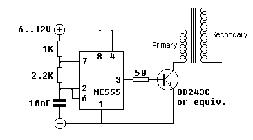
Following schematic is nothing more than the standard astable mode circuit
design with a classic 555. It requires only two resistors and a capacitor to set
frequency (with duty cycle of course) and another resistor to determine power
transistor’s base current, which you can find it’s optimal value experimentally.
I used 1K for R1, 2.2K for R2, and 10nF for C which made circuit to run nearly
at 27 kHz theoretically, at %60 high to %40 low duty cycle. You can quickly
calculate operating parameters from the resistance and capacitor values with a
small program that I’ve written

No comments:
Post a Comment