This circuit is a rat and cockroach repeller which use principle of
sound waves or ultrasonic cause they annoyed so it escaped away. This is
small and cheap because use transistor (no ICs) and super loud since
use large piezoelectric but use low current source.
Technical information
- Use power supply of 9 Vdc.
- Maximum consumption current about 48 mA
- PCB size : 2.25 x 1.57 inch.
- With trimmer to adjust the tone.
- PCB dimensions: 2.11 x 1.66 inches.
- Adjust the speed of the sound spectrum from 10-33 kHz.
The working of circuit
As Figure 1 in this circuit will have two monostable multivibrators. In frist set will consists of TR1 and TR2 are used to generate a low frequency by have C2, C3, R1-R4, LED and VR- 100K, which it is the frequencies generators to Collector of TR2.

Figure 1 Rat and cockroach repeller circuit diagram.
LED will is used for power on display of this project. And VR-100K will be adjustable of timing range. The low frequency will be sent to control the high frequency generator. Which consist of TR3 and TR4 and R5-R8, C5, C6 will be combine to increasing frequency rises up. Before send to piezo speaker next.
In this the frequency generator will work according to the rhythm, The performance of low-frequency generator. We heard a sound out of the speakers at intervals.
How to build its.
As Figure 2 is the components layout and wiring of this projects. Now I am sorry not have the PCB layout but you may use the perforated board or Universal PCB board as circuit diagram.

Figure 2 the components layout and wiring

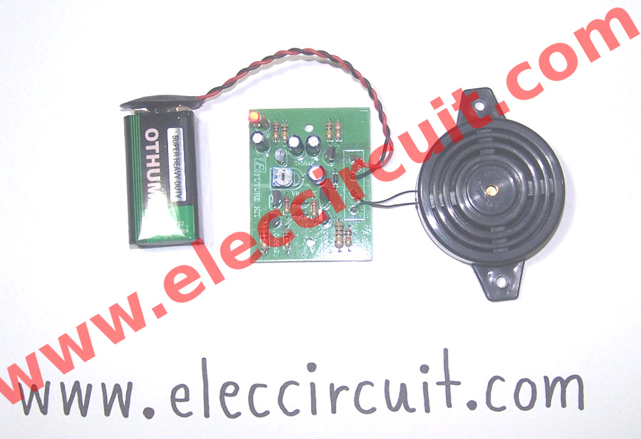
As Figure 3 we assemble the parts of this projects are successful.
Testing
Check the every devices that is accurate. If ensure that the correct. To connecting the piezo speaker to PZ point. Then rotate VR 100K to left end.
Next apply a 9 volts supply to 9V point by correct polarity, Otherwise, it may cause circuit damage.
When we apply power supply voltage to the circuit, we will hear frequency sound out of speaker at intervals, along with LED lights intermittently as well.
Figure 4 is video test sound of Rat and cockroach repeller circuit.
Then try to adjust VR-100K to the right hand fully the sounds that we hear from time to time will slow down.
If, as this indicates that the circuit is ready for use. In real applications Should be changed weekly frequency Because if no adjustment Rats and cockroaches habituate to the frequency. Make them ineffective.
The Parts list.
RESISTORS
R1_______________2K
R2, R3____________100K
R4________________3.9K
R5, R8_____________10K
R6, R7_____________22K
R9, R10____________500 ohm
TRIMMER POTENTIOMETER
VR1_______________100K(104 code)
ELECLTROLYTIC CAPACITORS
C1________________47uF
C2________________10uF
R3________________22uF
C4________________100uF
CERAMIC CAPACITORS
C5, C6_____________820pF
DIODE
D1________________1N4148
TRANSISTORS
TR1-TR6_________2SC458, 2SC828, 2SC945, 2SC1815
Technical information
- Use power supply of 9 Vdc.
- Maximum consumption current about 48 mA
- PCB size : 2.25 x 1.57 inch.
- With trimmer to adjust the tone.
- PCB dimensions: 2.11 x 1.66 inches.
- Adjust the speed of the sound spectrum from 10-33 kHz.
The working of circuit
As Figure 1 in this circuit will have two monostable multivibrators. In frist set will consists of TR1 and TR2 are used to generate a low frequency by have C2, C3, R1-R4, LED and VR- 100K, which it is the frequencies generators to Collector of TR2.
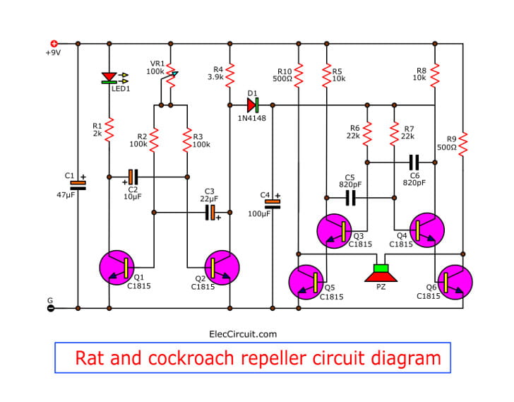
Figure 1 Rat and cockroach repeller circuit diagram.
LED will is used for power on display of this project. And VR-100K will be adjustable of timing range. The low frequency will be sent to control the high frequency generator. Which consist of TR3 and TR4 and R5-R8, C5, C6 will be combine to increasing frequency rises up. Before send to piezo speaker next.
In this the frequency generator will work according to the rhythm, The performance of low-frequency generator. We heard a sound out of the speakers at intervals.
How to build its.
As Figure 2 is the components layout and wiring of this projects. Now I am sorry not have the PCB layout but you may use the perforated board or Universal PCB board as circuit diagram.
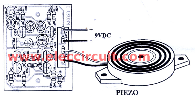
Figure 2 the components layout and wiring
As Figure 3 we assemble the parts of this projects are successful.
Testing
Check the every devices that is accurate. If ensure that the correct. To connecting the piezo speaker to PZ point. Then rotate VR 100K to left end.
Next apply a 9 volts supply to 9V point by correct polarity, Otherwise, it may cause circuit damage.
When we apply power supply voltage to the circuit, we will hear frequency sound out of speaker at intervals, along with LED lights intermittently as well.
Figure 4 is video test sound of Rat and cockroach repeller circuit.
Then try to adjust VR-100K to the right hand fully the sounds that we hear from time to time will slow down.
If, as this indicates that the circuit is ready for use. In real applications Should be changed weekly frequency Because if no adjustment Rats and cockroaches habituate to the frequency. Make them ineffective.
The Parts list.
RESISTORS
R1_______________2K
R2, R3____________100K
R4________________3.9K
R5, R8_____________10K
R6, R7_____________22K
R9, R10____________500 ohm
TRIMMER POTENTIOMETER
VR1_______________100K(104 code)
ELECLTROLYTIC CAPACITORS
C1________________47uF
C2________________10uF
R3________________22uF
C4________________100uF
CERAMIC CAPACITORS
C5, C6_____________820pF
DIODE
D1________________1N4148
TRANSISTORS
TR1-TR6_________2SC458, 2SC828, 2SC945, 2SC1815
No comments:
Post a Comment