Send sound waves as mosquito repellents by generating a small sound
frequencies on transistor based bistable multivibrator. Which is
economical and safe. In the use of chemicals.
Mosquitoes, in addition to the already annoyed. Also carriers of pathogens that cause harm to human beings. Which normally we get rid of mosquitoes with chemicals. It has worked great, but if you use it regularly, it affects our body naturally.
Which method is safe?
This project used sound mosquito repellents, is the safest way, for health. Because,We create high frequency sound waves that mosquitoes do not like. According to the theory of the scientists found that Mosquitoes do not high frequency sound waves. And to fly away because it interferes with its flight.
How this circuit works
In Figure 1 The circuit uses two transistors (Q1,Q2) connects to the transistor based bistable multivibrator oscillator generate a sound frequency. Which, a sound of this circuit is determined by both resistors(R2, R3) and both capacitors(C1, C2) connected with together . The sound frequency that out of a collector pin of Q2-transistor to ceramic piezo sounder to emit a high sound wave go out , on radius of under 5 square meter.
If is outdoor or mosquito disturb too much. so, put this project far from us around 1 meter.

Figure 1 the Simple-mosquito repellent circuit use the transistor based bistable multivibrator
How to builds
A creating easily due to the circuit use a few components. assemble it so has the PCB layout as shown Figure 2 while photo show putting components layout. should solder into as proper position. For value of circuit should matched as circuit defined . then , so cut devices leg, next solder them to PCB and connecting all wires.
Characteristics of the piezo speaker, is a metal thin circular. One side coated with ceramic in different sizes are 15, 20, 25, 30, 35, 40 and 50 millimeter.

Figure 2 PCB an components layout of this projects.
Testing and application
First of all, connect correctly a positive-negative voltage polarity. By use a 1.5 volts from a common battery. If correct circuit, next connect battery, then turn on S1-switch. we will hear high frequency tone out off the piezo speaker is weak. indicate this project is working now.
Then, turn on this circuit for about 30 minutes. and then Placed a mosquito infestation. After approximately 30 minutes. Mosquitoes will be less indicated are the equipment is good.
But if also Many mosquitoes are the same.We think that this frequency may have no effect on mosquitoes. Which we can easily change frequency of sound tone, with changes a capacitance of C2 in circuit from 0.002 microfarad into 0.0022 microfarad or lower is 0.0015 microfarad. and then observed changes in mosquitoes.
Components list
Resistors ¼ watts + 5%
R1, R4——————————-1.5 Kohm
R2, R3——————————-100 Kohm
Capacitors
C1————————————560pF 50V polyestcer
C2————————————0.002uF 50V polyestcer
Semiconductor
Q1, Q2——————————2SC9013-NPN type
Others
P1—piezo speaker 35mm.
S1— switch ON-OFF
Battery 1.5V , PCB, Wires, Box , etc.
Mosquitoes, in addition to the already annoyed. Also carriers of pathogens that cause harm to human beings. Which normally we get rid of mosquitoes with chemicals. It has worked great, but if you use it regularly, it affects our body naturally.
Which method is safe?
This project used sound mosquito repellents, is the safest way, for health. Because,We create high frequency sound waves that mosquitoes do not like. According to the theory of the scientists found that Mosquitoes do not high frequency sound waves. And to fly away because it interferes with its flight.
How this circuit works
In Figure 1 The circuit uses two transistors (Q1,Q2) connects to the transistor based bistable multivibrator oscillator generate a sound frequency. Which, a sound of this circuit is determined by both resistors(R2, R3) and both capacitors(C1, C2) connected with together . The sound frequency that out of a collector pin of Q2-transistor to ceramic piezo sounder to emit a high sound wave go out , on radius of under 5 square meter.
If is outdoor or mosquito disturb too much. so, put this project far from us around 1 meter.
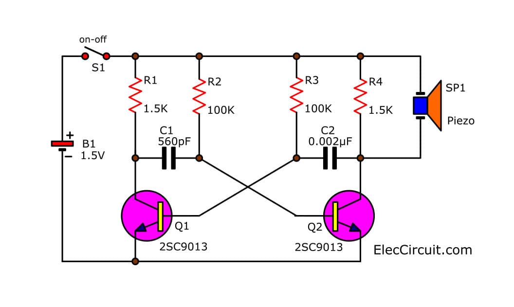
Figure 1 the Simple-mosquito repellent circuit use the transistor based bistable multivibrator
How to builds
A creating easily due to the circuit use a few components. assemble it so has the PCB layout as shown Figure 2 while photo show putting components layout. should solder into as proper position. For value of circuit should matched as circuit defined . then , so cut devices leg, next solder them to PCB and connecting all wires.
Characteristics of the piezo speaker, is a metal thin circular. One side coated with ceramic in different sizes are 15, 20, 25, 30, 35, 40 and 50 millimeter.

Figure 2 PCB an components layout of this projects.
Testing and application
First of all, connect correctly a positive-negative voltage polarity. By use a 1.5 volts from a common battery. If correct circuit, next connect battery, then turn on S1-switch. we will hear high frequency tone out off the piezo speaker is weak. indicate this project is working now.
Then, turn on this circuit for about 30 minutes. and then Placed a mosquito infestation. After approximately 30 minutes. Mosquitoes will be less indicated are the equipment is good.
But if also Many mosquitoes are the same.We think that this frequency may have no effect on mosquitoes. Which we can easily change frequency of sound tone, with changes a capacitance of C2 in circuit from 0.002 microfarad into 0.0022 microfarad or lower is 0.0015 microfarad. and then observed changes in mosquitoes.
Components list
Resistors ¼ watts + 5%
R1, R4——————————-1.5 Kohm
R2, R3——————————-100 Kohm
Capacitors
C1————————————560pF 50V polyestcer
C2————————————0.002uF 50V polyestcer
Semiconductor
Q1, Q2——————————2SC9013-NPN type
Others
P1—piezo speaker 35mm.
S1— switch ON-OFF
Battery 1.5V , PCB, Wires, Box , etc.
I would like to thank you for the efforts you have made in writing this article. I am hoping the same best work from you in the future as well. Thanks... notrac blox
ReplyDeleteWow, What a Excellent post. I really found this to much informatics. It is what i was searching for.I would like to suggest you that please keep sharing such type of info.Thanks trappole per mosche
ReplyDelete