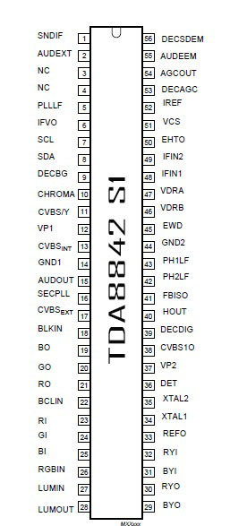
LG COLOUR TV CHROMA IC TDA 8842 S1
 |
| tda 8842s1 |
SNDIF 1 Sound IF input
AUDIOEXT 2 External audio input
NC 3 not connected
NC 4 not connected
PLLLF 5 IF-PLL loop filter
IFVO 6 IF video output
SCL 7 serial clock input
SDA 8 serial data input/output
DECBG 9 bandgap decoupling
CHROMA 10 chrominance input (S-VHS)
CVBS/Y 11 external CVBS/Y input
VP1 12 main supply voltage 1 (+8 V)
CVBSINT 13 internal CVBS input
GND1 14 ground 1
AUDIOOUT 15 audio output
SECPLL 16 SECAM PLL decoupling
CVBSEXT 17 external CVBS input
BLKIN 18 black-current input
BO 19 blue output
GO 20 green output
RO 21 red output
BCLIN 22 beam current limiter input/V-guard input
RI 23 red input for insertion
GI 24 green input for insertion
BI 25 blue input for insertion
RGBIN 26 RGB insertion input
LUMIN 27 luminance
LUMOUT 28 luminance output
BYO 29 (B-Y) signal output
RYO 30 (R-Y) signal output
BYI 31 (B-Y) signal input
RYI 32 (R-Y) signal input
REFO 33 subcarrier reference output
XTAL1 34 3.58 MHz crystal connection
XTAL2 35 4.43/3.58 MHz crystal connection
DET 36 loop filter phase detector
VP2 37 2nd supply voltage 1(+8 V)
CVBS1O 38 CVBS-1 output
DECDIG 39 Decoupling digital supply
HOUT 40 horizontal output
FBISO 41 flyback input/sandcastle output
PH2LF 42 phase-2 filter
PH1LF 43 phase-1 filter
GND2 44 ground 2
EWD 45 east-west drive output
VDRB 46 vertical drive B output
VDRA 47 vertical drive A output
IFIN1 48 IF input 1
IFIN2 49 IF input 2
EHTO 50 EHT/overvoltage protection input
VSC 51 vertical sawtooth capacitor
Iref 52 reference current input
DECAGC 53 AGC decoupling capacitor
AGCOUT 54 tuner AGC output
AUDEEM 55 Audio deemphasis
DECSDEM 56 Decoupling sound demodulator
tda 8842s1 DATASHEET tda8842 pin voltage tda8842 circuit diagram tda8842 pin details tda8841 circuit diagram datasheet tda8844 circuit diagram datasheet tda8844 protection pin
AUDIOEXT 2 External audio input
NC 3 not connected
NC 4 not connected
PLLLF 5 IF-PLL loop filter
IFVO 6 IF video output
SCL 7 serial clock input
SDA 8 serial data input/output
DECBG 9 bandgap decoupling
CHROMA 10 chrominance input (S-VHS)
CVBS/Y 11 external CVBS/Y input
VP1 12 main supply voltage 1 (+8 V)
CVBSINT 13 internal CVBS input
GND1 14 ground 1
AUDIOOUT 15 audio output
SECPLL 16 SECAM PLL decoupling
CVBSEXT 17 external CVBS input
BLKIN 18 black-current input
BO 19 blue output
GO 20 green output
RO 21 red output
BCLIN 22 beam current limiter input/V-guard input
RI 23 red input for insertion
GI 24 green input for insertion
BI 25 blue input for insertion
RGBIN 26 RGB insertion input
LUMIN 27 luminance
LUMOUT 28 luminance output
BYO 29 (B-Y) signal output
RYO 30 (R-Y) signal output
BYI 31 (B-Y) signal input
RYI 32 (R-Y) signal input
REFO 33 subcarrier reference output
XTAL1 34 3.58 MHz crystal connection
XTAL2 35 4.43/3.58 MHz crystal connection
DET 36 loop filter phase detector
VP2 37 2nd supply voltage 1(+8 V)
CVBS1O 38 CVBS-1 output
DECDIG 39 Decoupling digital supply
HOUT 40 horizontal output
FBISO 41 flyback input/sandcastle output
PH2LF 42 phase-2 filter
PH1LF 43 phase-1 filter
GND2 44 ground 2
EWD 45 east-west drive output
VDRB 46 vertical drive B output
VDRA 47 vertical drive A output
IFIN1 48 IF input 1
IFIN2 49 IF input 2
EHTO 50 EHT/overvoltage protection input
VSC 51 vertical sawtooth capacitor
Iref 52 reference current input
DECAGC 53 AGC decoupling capacitor
AGCOUT 54 tuner AGC output
AUDEEM 55 Audio deemphasis
DECSDEM 56 Decoupling sound demodulator
Other ic datas are available in this link
tda 8842s1 DATASHEET tda8842 pin voltage tda8842 circuit diagram tda8842 pin details tda8841 circuit diagram datasheet tda8844 circuit diagram datasheet tda8844 protection pin
No comments:
Post a Comment